
Southern African Development Community
(SADC)
Water Sector Coordination Unit
(WSCU)
Funded by the Government of France
Development of a Code of Good Practice for Groundwater
Development in the SADC Region
REPORT No.2 (Final)
GUIDELINES FOR THE GROUNDWATER DEVELOPMENT
IN THE SADC REGION
November 2001
GROUNDWATER CONSULTANTS
Bee Pee (Pty) Ltd.
P.O. Box 7885
Maseru 100
Lesotho
Southern African Development Community
(SADC)
Water Sector Coordination Unit
(WSCU)
Funded by the Government of France
PROJECT
Development of a Code of Good Practice for Groundwater
Development in the SADC Region
REPORT No.2 (Final)
TITLE
GUIDELINES FOR THE GROUNDWATER DEVELOPMENT
IN THE SADC REGION
November 2001
FOREWORD
On behalf of the Southern African Development Community (SADC) Water Sector, I
have the honour of presenting this document entitled "A Code of Good Practice and
Guidelines for Groundwater Development in the SADC Region".
The member States of SADC have agreed to cooperate on strategic sectors that will
contribute to and foster regional economical development and integration on the basis
of balance, equity and mutual benefit for all member States. As a result the Water
Sector was identified as one of such strategic sectors and thus was established in
1996, and coordination responsibility was given to the Kingdom of Lesotho. The
overall objective of the Water Sector is to promote cooperation in all water matters in
the region for sustainable and equitable utilisation, development and management of
water resources that contribute towards the upliftment of the quality of life of the
people of the SADC region.
There are a number of challenges faced by the Water Sector in order to meet its
objective that require concerted efforts by all member States to avert the effects of
those challenges. The major challenges that need to be addressed include the
provision of water of adequate quantity and quality and safe sanitation services
mainly to the people living in rural areas of the region, the majority of which still lack
access to these basic services.
A number of documented studies have shown that more than 60% of communities in
the region depend on groundwater, of which the majority (about 70%) live in rural
areas. Studies have also shown that two or more countries share a number of aquifers
from which water is abstracted for various purposes and services in member States.
The SADC Water Sector therefore acknowledges that groundwater resources are
finite and valuable and are recognised as playing a pivotal role in activities aimed at
alleviating or combating poverty in the region. The SADC Water Sector also
acknowledges that all member States are at different levels in terms of management
and development systems used in managing and developing groundwater resources as
shown by documented studies. Therefore proper development and management
systems need to be in place in order to jointly manage and harness this resource in an
economically, environmentally and socially sustainable manner. This is also in
pursuance of the Protocol on Shared Watercourses in the SADC Region underlying
joint water resources management principle.
The SADC Water Sector Coordinating Unit with the Water Sector Stakeholders in an
effort to address some of the concerns raised above, have attempted to put in place
preliminary management and development tools and mechanisms to be used by a
variety of agencies involved in the groundwater management and development
ranging from government departments, consultants and drilling companies. The
process leading to the development of this document has been very consultative and
has also involved a number of stakeholders in all SADC member States, including
other SADC Sectors such as the Trade and Industry Sector. Processes are underway
for the Trade and Industry Sector having the mandate of developing "Standards" for
the region to adopt this document.
The SADC Water Sector views this document as an on-going evolutionary process
with evolving technology, and therefore will continue consultations with a wider
range of stakeholders in an effort to improve this document through regular reviews.
We, therefore, appeal to and encourage all agencies involved in water resources
development and management to take cognisance of this document when developing
and managing groundwater resources. We also hope that the implementation and the
application of this Code of Good Practice and Guidelines will prove an effective
management and development approach for this resource.
The SADC Water Sector acknowledges the commitment and contribution of the
member States in this document. The SADC Water Sector is also most grateful to the
French Government for financial and technical support that made it possible to
produce this document.
........................
Phera S. Ramoeli
Chief Engineer Ł Sector Coordinator
SADC Water Sector.
PREFACE
The project goal was to develop minimum common standards for groundwater development
in the Southern African Development Community (SADC) Member States, which would serve
as regional standards and guidelines to maintain uniform, good quality development in a
cost-effective manner. Implementation of the project is by the SADC Water Sector
Coordination Unit (SADC-WSCU) through the financial assistance of the French
Government. Groundwater Consultants (Pty) Ltd were commissioned to carry out the project
on behalf of SADC-WSCU.
SADC adopted a Regional Groundwater Management Programme (RGMP) consisting of 10
Projects within the overall framework of regional co-operation and development. The present
project was identified as the priority project for implementation.
To accomplish the project objectives the project was divided into two interdependent stages.
Stage 1 was basically the fact finding, data collection and situation analysis stage, while
Stage 2 focussed on the drafting of standards and guidelines based on the feedback received
during Stage 1.
The Stage 1 Report (Report No.1) was submitted and discussed in a workshop (Workshop
No.1) with the Hydrogeology Subcommittee on 25th and 26th September' 2000. It was agreed
in the meeting that the Report No.1 contains useful information for reference and therefore
should be produced in final form as a reference report to Report No.2.
The Draft Final Report of stage 2 (Report No.2) was submitted in February 2001. The report
was presented to the Hydrogeology Subcommittee on 27th and 28th March 2001 in a workshop
in Mauritius (Workshop No.2). Apart from the subcommittee members, the workshop was also
attended by the SADC STAN (SADC Cooperation in Standardization) experts as observers.
The present Final Report No.2 incorporates the comments and suggestions raised during the
workshop on the Draft Final Report.
During the Workshop No.1, there was a significant discussion on the use of the term
`Minimum Standard' versus `guidelines'. The primary difference between the terms being that
`standard', although effecting only voluntary compliance, has a more strict connotation to
most than the term `guideline', which implies more flexibility in implementation. At the time,
no specific consensus was reached on the preferred use of either term.
Similar to Workshop No.1, there was some discussion on the title of the report, following the
SADC STAN presentation that apprised the committee of the definition of the words,
`Standards', Guidelines' and `Code of Practice' during the Workshop No. 2. `Standards'
refer to a technical document that prescribes the quality characteristics of a product for it to
meet its intended use, while `Code of Practice' refers to a document that recommends
practices or procedures for the design, manufacture, installation, maintenance or utilisation
of equipment, structures or products. Therefore, a consensus was reached on the term `Code
of Practice' instead of `Standards'.
Following the presentation on the regional process of harmonisation of standards within the
SADC Region by the SADC STAN experts, it was realised that the present work on
groundwater standards needs to be incorporated within the framework of SADC STAN. It was
agreed that the present report should become a basis for the adoption of these groundwater
standards and guidelines as the formal `Code of Practice' by the SADC STAN through its
protocol. Therefore the document should be titled "Guidelines for the Groundwater
Development in the SADC Region" under the project title of "Development of a Code of
Good Practice for Groundwater Development in the SADC Region".
This `Code of Good Practice' document is very focused on technical aspects and recommends
the correct practices and/or procedures in relation to groundwater development. By and
large, the document follows sequentially the logical steps in a typical groundwater
development programme, starting from project implementation and planning until the
borehole equipping and reporting. In general, the rationale behind the recommendations and
current practices in the region is not discussed in this document. For this the reader is
referred to Report No.1 and other technical references provided with this document.
In the present document a word `desirable' has also been used frequently in relation to the
standards and guidelines. The standards and guidelines in this document refer to the
minimum level that should be implemented during groundwater development. In certain cases
it may be possible to easily improve the quality of works or data collected, and/or gain
additional confidence in results by implementing extra measures, that in some cases have
additional cost implications. In this report, these activities or procedures are defined as
`desirable'.
Implementing these codes of practice can have profound implications for advancement of the
hydrogeological science through improved integration of data collection and development
practices across national boundaries. Not only will it facilitate the institution of a proper
code of practice that will serve the end user much better, but it will also result in enhanced
exchange of resources across the region, be it technical, manpower, data, or equipment and
instruments.
In the opinion of the authors, this comprehensive document is a valuable guide in
groundwater project implementation in addition to setting a minimum level for groundwater
development practices. The intention of this document is not to rigidly enforce, but to
facilitate and improve the quality of, groundwater development as per the current state of the
science. This document further has the advantage of using terminology and reflecting
conditions that are common in (and sometimes specific to) the SADC region.
The need for this document is also appreciated in view of the considerable variation in the
level of groundwater development activities in the region, from poor or inappropriate to
extremely effective and sophisticated methodologies. In essence, it is desirable to have certain
Minimum Common Standards and Guidelines for optimal and sustainable development and
management of groundwater resources with the ultimate purpose of providing services to the
majority of the population in the region and providing maximum benefit to future generations.
It is important that this document be seen not as a static object but as an on-going,
evolutionary process. As such, regular review and up-dating of the document is imperative if
this first comprehensive document is to continue to serve the overall objective of effectively
implementing Regional Groundwater Management Programme for the SADC Region.
ACKNOWLEDGEMENTS
This document is a part of the Regional Groundwater Management Programme for the SADC Region.
The document is drafted by Groundwater Consultants, Bee Pee (Pty) Ltd. of Maseru, Lesotho under a
project of the SADC Water Sector. The project was managed by the SADC Water Sector Coordination
Unit (SADC-WSCU) of Maseru Lesotho, with technical back-up from the SADC Sub-Committee for
Hydrogeology, acting as Steering Committee for the Project.
The French Government (Ministry of Foreign Affairs, Cooperation and Francophony), under a Grant
agreement with SADC, provided the source of funding for the project to SADC-WSCU.
Consultant Team
M M Bakaya Ł Project Director
T B Bakaya Ł Quality Reviewer
S K Pandey Ł Consultant
F Linn Ł Consultant
D Juizo Ł Consultant
A Simmonds - Consultant
F Greiner Ł Consultant
Steering Committee
Mr. P S Ramoeli (Coordinator, SADC WASCU)
Ms P Molapo (Senior Engineer- Groundwater, SADC-WSCU)
Dr. S Puyo¶ (Technical Advisor to SADC-WSCU under the French Assistance Programme)
Mr. G M Christelis (Chairperson, Namibia)
Ms. L Mokoena (Vice-chairperson, South Africa)
Mr. P J da Silva (Angola)
Mr. O Katai (Botswana)
Mr. M Tchimoa (Democratic Republic of Congo)
Mr. M Lesupi (Lesotho)
Mr. J T Banda (Malawi)
Mr. R Pokhun (Mauritius)
Mr. L A Chairuca (Mozambique)
Mr. D Labodo (Seychelles)
Ms. L Mokoena (South Africa)
Mr. O Ngwenya (Swaziland)
Mr. F Senguji (Tanzania)
Mr. L O Sangulube (Zambia)
Mr. L Sengayi (Zimbabwe)
Observers
The following members were observers and provided significant contribution and guidance on the
process:
Mr. B Aleobua (DWAF, South Africa)
Mr. M Chetty (SADC STAN Member, SABS, South Africa)
Mr. S Khodabux (SADC STAN Member, MSB, Mauritius)
Ms C Colvin (IAH Deputy Chairperson for Sub-Sahara Africa)
Mr. K Sami (Council for Geosciences, South Africa)
Mr. G Small (Council for Geosciences, South Africa)
Mr. B Kumwenda (SADC Mining Sector, Zambia)
Mr. R Ndhlovu (Geological Survey Department, Zambia)
Mrs. N Masuku (Geological Survey Department, Zimbabwe)
Document Ownership and Copyrights
This document is owned by the SADC WSCU. No part of this document should be reproduced in any
manner without full acknowledgement of the source.
The document is obtainable from the SADC WSCU, Ministry of Natural Resources, P/Bag A-440,
Maseru 100, Lesotho; Tel (+266) 310022; e-mail: sadcwscu@lesoff.co.za
MAIN REPORT
Development of a Code of Good Practice for Groundwater
Final Report
Development in the SADC Region
TABLE OF CONTENTS
SECTION 1:
GUIDELINES ON GROUNDWATER PROJECT
IMPLEMENTATION.............................................................................. 1-1
1.1
GENERAL ................................................................................................................ 1-1
1.1.1
Scope and Purpose ..................................................................................... 1-1
1.2
ROLE PLAYERS ....................................................................................................... 1-1
1.2.1
National Groundwater Regulatory Body (NGRB)...................................... 1-1
1.2.2
The Implementing Agency (IA)................................................................... 1-3
1.2.3
The Executing Agency ................................................................................ 1-3
1.3
IMPLEMENTATION STRATEGY ................................................................................ 1-3
1.3.1
Community Participation and Need Assessment ........................................ 1-3
1.3.2
Feasibility Study ......................................................................................... 1-4
1.3.3
Proposal and Financing ............................................................................. 1-5
1.3.4
Project Plan and Preparation of Tender Documents................................. 1-6
1.3.5
Tendering and Appointment of Executing Agencies................................... 1-7
1.3.6
Manpower Resource Input and Management Structure............................. 1-7
1.3.7
Execution of Groundwater Development Project..................................... 1-11
1.3.8
Monitoring and Evaluation (M&E).......................................................... 1-11
1.4
PRIVATE BOREHOLES ........................................................................................... 1-13
1.5
DATA CAPTURE AND MANAGEMENT ................................................................... 1-14
1.5.1
Recording Forms ...................................................................................... 1-14
1.5.2
Coordination............................................................................................. 1-14
1.5.3
Borehole Numbering System .................................................................... 1-15
1.5.4
Record Keeping and Data Management .................................................. 1-16
1.6
REGISTRATION OF CONSULTANTS AND CONTRACTORS....................................... 1-16
SECTION 2:
DESK STUDY AND RECONNAISSANCE SURVEY ......................... 2-1
2.1
GENERAL ................................................................................................................ 2-1
2.1.1
Scope and Purpose ..................................................................................... 2-1
2.2
BACKGROUND INFORMATION................................................................................. 2-1
2.2.1
Legal Aspects.............................................................................................. 2-1
2.2.2
Environmental Aspects ............................................................................... 2-1
2.2.3
Physical ...................................................................................................... 2-1
2.3
DESK STUDY........................................................................................................... 2-1
2.3.1
Existing Borehole Information ................................................................... 2-2
2.3.2
Maps ........................................................................................................... 2-2
2.3.3
Water Quality Analyses .............................................................................. 2-2
2.3.4
Existing Reports.......................................................................................... 2-3
2.3.5
Aerial Photograph Review ......................................................................... 2-3
2.3.6
Pumping-test Data...................................................................................... 2-3
2.3.7
Tentative Borehole Design ......................................................................... 2-3
2.3.8
Additional Activities ................................................................................... 2-4
2.4
RECONNAISSANCE FIELD SURVEY ......................................................................... 2-4
2.5
ADDITIONAL ACTIVITIES........................................................................................ 2-5
2.5.1
Limited Hydrogeologic Mapping / Data Collection................................... 2-5
2.5.2
Water Point Inventory ................................................................................ 2-5
2.6
TARGET AREA DELINEATION ................................................................................. 2-5
SECTION 3:
BOREHOLE SITING .............................................................................. 3-1
3.1
GENERAL ................................................................................................................ 3-1
3.1.1
Scope and Purpose ..................................................................................... 3-1
3.1.2
Principle ..................................................................................................... 3-1
3.2
CONTROLLING FACTORS ........................................................................................ 3-1
SADC Water Sector Coordination Unit, Lesotho
i
Development of a Code of Good Practice for Groundwater
Final Report
Development in the SADC Region
3.2.1
Legal Aspects.............................................................................................. 3-1
3.2.2
Social Aspect .............................................................................................. 3-1
3.2.3
Accessibility................................................................................................ 3-1
3.2.4
Environmental Aspects ............................................................................... 3-2
3.2.5
Yield Requirement ...................................................................................... 3-2
3.3
SITING TECHNIQUES AND METHODS ...................................................................... 3-2
3.3.1
Geological and Hydrogeological Technique.............................................. 3-2
3.3.2
Geophysical Techniques............................................................................. 3-3
3.4
MISCELLANEOUS .................................................................................................... 3-5
3.4.1
Number of Sites........................................................................................... 3-5
3.4.2
Prioritisation of Sites.................................................................................. 3-5
3.4.3
Marking of Sites.......................................................................................... 3-5
3.4.4
Site Selection Forms ................................................................................... 3-5
SECTION 4:
BOREHOLE DRILLING AND CONSTRUCTION............................. 4-1
4.1
GENERAL ................................................................................................................ 4-1
4.1.1
Scope and Purpose ..................................................................................... 4-1
4.1.2
Pre-requisite for Drilling of Boreholes ...................................................... 4-1
4.1.3
Supervision of Drilling ............................................................................... 4-1
4.1.4
Data Recording .......................................................................................... 4-1
4.1.5
Pre-mobilisation Meeting/Agreement......................................................... 4-1
4.2
DRILLING ................................................................................................................ 4-2
4.2.1
Choice of Drilling Method.......................................................................... 4-2
4.2.2
Drilling Equipment..................................................................................... 4-4
4.2.3
Formation Sampling and Record Keeping ................................................. 4-4
4.2.4
Drilling Fluids............................................................................................ 4-6
4.2.5
Drilling Diameter ....................................................................................... 4-7
4.2.6
Monitoring During Drilling Activities........................................................ 4-7
4.2.7
Borehole Geophysical Logging .................................................................. 4-8
4.3
BOREHOLE CONSTRUCTION.................................................................................... 4-9
4.3.1
Casings ....................................................................................................... 4-9
4.3.2
Screens...................................................................................................... 4-10
4.3.3
Typical Borehole Designs......................................................................... 4-12
4.3.4
Installation of Casing and Screens........................................................... 4-16
4.3.5
Gravel Pack.............................................................................................. 4-16
4.3.6
Grouting and Sealing ............................................................................... 4-18
4.3.7
Verticality and Alignment......................................................................... 4-18
4.4
BOREHOLE DEVELOPMENT................................................................................... 4-19
4.5
BOREHOLE DISINFECTION .................................................................................... 4-19
4.6
SITE COMPLETION ................................................................................................ 4-19
4.7
MISCELLANEOUS............................................................................................. 4-20
4.7.1
Drilling Site .............................................................................................. 4-20
4.7.2
Abandonment of Boreholes....................................................................... 4-20
SECTION 5:
BOREHOLE DEVELOPMENT............................................................. 5-1
5.1
GENERAL ................................................................................................................ 5-1
5.1.1
Scope and Purpose ..................................................................................... 5-1
5.1.2
Principles.................................................................................................... 5-1
5.1.3
Choice of Development Method ................................................................. 5-1
5.2
MECHANICAL DEVELOPMENT METHODS ............................................................... 5-2
5.2.1
Pumping Methods....................................................................................... 5-3
5.2.2
Surging Methods......................................................................................... 5-4
5.2.3
Jetting Methods .......................................................................................... 5-6
5.3
CHEMICAL METHODS ............................................................................................. 5-7
5.4
TESTING COMPLETENESS OF DEVELOPMENT ......................................................... 5-8
SADC Water Sector Coordination Unit, Lesotho
ii
Development of a Code of Good Practice for Groundwater
Final Report
Development in the SADC Region
5.4.1
Air Lift Pumping......................................................................................... 5-8
5.4.2
Short Constant Rate Test ............................................................................ 5-9
5.4.3
Short Step Test............................................................................................ 5-9
5.5
BOREHOLE ACCEPTANCE ....................................................................................... 5-9
SECTION 6:
GROUNDWATER SAMPLING............................................................. 6-1
6.1
GENERAL ................................................................................................................ 6-1
6.1.1
Scope and Purpose ..................................................................................... 6-1
6.2
THE SAMPLING PROGRAMME .................................................................................. 6-1
6.2.1
Single Water Point Sampling...................................................................... 6-1
6.2.2
Multiple Water Point Sampling .................................................................. 6-1
6.2.3
Laboratory Liaison..................................................................................... 6-2
6.3
GROUNDWATER SAMPLING METHODS................................................................... 6-2
6.3.1
Sample Collecting Devices ......................................................................... 6-2
6.3.2
Spring Sampling ......................................................................................... 6-3
6.3.3
Existing Borehole and Hand Dug Well Sampling ...................................... 6-3
6.3.4
New Borehole Sampling ............................................................................. 6-3
6.3.5
Multiple Horizon Sampling ........................................................................ 6-4
6.3.6
Preservation Methods................................................................................. 6-4
6.3.7
Labelling and Documentation .................................................................... 6-4
6.3.8
Analysis ...................................................................................................... 6-5
SECTION 7:
PUMPING TEST OF BOREHOLES ..................................................... 7-1
7.1
GENERAL ................................................................................................................ 7-1
7.1.1
Scope and Purpose ..................................................................................... 7-1
7.1.2
Conducting And Supervising the Pumping Test Operations ...................... 7-1
7.2
TYPES OF TESTS...................................................................................................... 7-2
7.3
CHOICE OF TYPE AND DURATION OF TEST............................................................. 7-3
7.4
PUMPING EQUIPMENT AND MATERIAL AND THEIR INSTALLATION .............. 7-4
7.4.1
Pumps ......................................................................................................... 7-4
7.4.2
Delivery Pipes ............................................................................................ 7-4
7.4.3
Discharge Control and Measuring Equipment .......................................... 7-5
7.4.4
Water Level Measurement Equipment........................................................ 7-6
7.4.5
Water Quality Monitoring Equipment........................................................ 7-6
7.5
PRE-TEST PREPARATIONS ....................................................................................... 7-7
7.5.1
Information to be collected......................................................................... 7-7
7.5.2
Pre-mobilization Meeting........................................................................... 7-7
7.5.3
Mobilisation and Installation of Test Unit ................................................. 7-7
7.5.4
Observation Boreholes/ Piezometers.......................................................... 7-8
7.6
PUMPING TEST ........................................................................................................ 7-8
7.6.1
Data and Records to be collected............................................................... 7-8
7.6.2
Testing ........................................................................................................ 7-9
7.7
MISCELLANEOUS .................................................................................................. 7-10
SECTION 8:
RECOMMENDATIONS ON PRODUCTION PUMPING.................. 8-1
8.1
GENERAL ................................................................................................................ 8-1
8.1.1
Scope and Purpose ..................................................................................... 8-1
8.2
REQUIRED PARAMETERS ........................................................................................ 8-1
8.2.1
Pumping test Data and Aquifer Parameters............................................... 8-1
8.2.2
Groundwater Recharge .............................................................................. 8-2
8.2.3
Groundwater Quality.................................................................................. 8-2
8.2.4
Abstraction Data from Nearby Production Boreholes ............................... 8-2
8.2.5
Monitoring Data......................................................................................... 8-2
8.2.6
Available Drawdown (sav) .......................................................................... 8-3
8.3
PRODUCTION PUMPING RECOMMENDATIONS ........................................................ 8-3
SADC Water Sector Coordination Unit, Lesotho
iii
Development of a Code of Good Practice for Groundwater
Final Report
Development in the SADC Region
8.3.1
Sustainable Yield ........................................................................................ 8-3
8.3.2
Pump Installation Depth........................................................................... 8-11
8.3.3
Water Quality ........................................................................................... 8-11
8.3.4
Water Quality Protection ......................................................................... 8-12
8.4
SPECIAL CONSIDERATIONS IN COASTAL AND INLAND SALINITY AREAS............ 8-12
8.5
ADJUSTMENTS IN PRODUCTION YIELD AND PUMPING HOURS AFTER
COMMISSIONING................................................................................................... 8-13
SECTION 9:
RECOMMENDATIONS ON EQUIPPING OF BOREHOLES .......... 9-1
9.1
GENERAL ................................................................................................................ 9-1
9.1.1
Scope and Purpose ..................................................................................... 9-1
9.2
BOREHOLES EQUIPPED WITH MOTORISED PUMPS................................................. 9-1
9.2.1
Design Requirements.................................................................................. 9-1
9.2.2
Pump Selection ........................................................................................... 9-1
9.2.3
Rising Mains............................................................................................... 9-3
9.2.4
Other Mechanical and Electrical Components .......................................... 9-4
9.2.5
Installation Of Pumping Equipment ........................................................... 9-4
9.3
BOREHOLES WITH NON-MOTORISED PUMPS.......................................................... 9-6
9.3.1
Handpumps................................................................................................. 9-6
9.3.2
Windmills.................................................................................................... 9-7
9.4
OPERATION AND MAINTENANCE............................................................................ 9-8
SECTION 10:
GUIDELINES ON HAND DUG WELLS AND SPRINGS ................ 10-1
10.1 HAND DUG WELLS ............................................................................................... 10-1
10.1.1
Siting......................................................................................................... 10-1
10.1.2
Well Excavation........................................................................................ 10-2
10.1.3
Well Lining ............................................................................................... 10-2
10.1.4
Installation of Liners ................................................................................ 10-3
10.1.5
Slotted or Perforated Pre-cast Concrete Rings, or in situ Cast Concrete
Liners. 10-4
10.1.6
Well Head Completion ............................................................................. 10-5
10.1.7
The Well Cover ......................................................................................... 10-5
10.1.8
Apron and Water Runoff Channel ............................................................ 10-6
10.1.9
Upgrading existing wells.......................................................................... 10-6
10.2 SPRINGS ................................................................................................................ 10-6
10.2.1
Spring Discharge (or Flow) and Water Quality Measurements .............. 10-6
10.2.2
Excavation of the Eye ............................................................................... 10-7
10.2.3
Spring Intake (Catchment) ....................................................................... 10-7
10.2.4
Water Supply System based on Spring Source ......................................... 10-9
10.2.5
Spring Catchment Protection and Monitoring ......................................... 10-9
10.2.6
Miscellaneous......................................................................................... 10-10
SECTION 11:
GUIDELINES ON REPORTING......................................................... 11-1
11.1 GENERAL .............................................................................................................. 11-1
11.1.1
Scope and Purpose ................................................................................... 11-1
11.2 REPORTING ........................................................................................................... 11-1
11.2.1
Inception Report ....................................................................................... 11-1
11.2.2
Siting Report or Site Selection Report...................................................... 11-2
11.2.3
Progress Reports ...................................................................................... 11-2
11.2.4
Final Report.............................................................................................. 11-2
11.2.5
Community Report.................................................................................... 11-3
SADC Water Sector Coordination Unit, Lesotho
iv
Development of a Code of Good Practice for Groundwater
Final Report
Development in the SADC Region
LIST OF TABLES
Table 1-1: Categorisitaion of Personnel Involved in a Typical Groundwater Development
Project/Programme ......................................................................................................... 1-7
Table 1-2 : Implementation Plan for Private Groundwater Development............................ 1-13
Table 4-1 : Summary of Drilling Methods ............................................................................. 4-3
Table 4-2 :Guidelines on Sampling Method .......................................................................... 4-5
Table 4-3: Types of Drilling Fluids........................................................................................ 4-6
Table 4-4 : Monitoring of Fluid Properties ............................................................................ 4-7
Table 4-5 : Characteristics of Sondes..................................................................................... 4-8
Table 4-6 :Screen Types....................................................................................................... 4-10
Table 5-1 : Borehole Development Methods and their Applicability .................................... 5-2
Table 5-2 : Orifice Size and Nozzle Pressure......................................................................... 5-6
Table 5-3 : Testing Methods to Assess Degree of Development .......................................... 5-8
Table 5-4 : Borehole Acceptance Criteria ............................................................................ 5-10
Table 6-1 : Minimum Requirements for Constituent Analysis .............................................. 6-5
Table 6-2 : Guidelines on Constituent Analysis..................................................................... 6-6
Table 7-1: Choice and Duration of Test ................................................................................. 7-3
Table 7-2 : Guidelines on Container Capacity for Discharge Measurements ........................ 7-5
Table 8-1 : Guidelines on Pumping Hours ........................................................................... 8-10
Table 9-1 : Guidelines on Pump Types .................................................................................. 9-2
Table 9-2 : Guidelines on Borehole Protection Structure....................................................... 9-4
Table 9-3 : Guidelines on Handpump Selection..................................................................... 9-6
SADC Water Sector Coordination Unit, Lesotho
v
Development of a Code of Good Practice for Groundwater
Final Report
Development in the SADC Region
LIST OF ANNEXES
Annex A : References
Annex B : Data Recording Forms
Annex C : Reference Material
SADC Water Sector Coordination Unit, Lesotho
vi
Development of a Code of Good Practice for Groundwater
Final Report
Development in the SADC Region
ACRONYMS
BS British
Standards
CBM
Community Based Management
CMAs
Catchment Management Authority
CRT
Constant Rate Test
CSIR
Council for Scientific and Industrial Research
DWAF
Department of Water Affairs and Forestry
DWAs
Departments of Water Affairs
EA Executing
Agency
EIA
Environmental Impact Assessment
ESAs
External Support Agencies
EU European
Union
FIDIC
International Federation of Consulting Engineers
GDs Geohydrology
Divisions
HLEM
Horizontal Loop Elecetro-magnetic
HTN
Handpump Technology Network
IA Implementing
Agency
IGS
Institute for Groundwater Studies
IP Induced
Polarisation
ISO
International Standards Organisation
NGOs
Non Governmental Organisations
NGRB
National Groundwater Regulating Body
SABS
South African Bureau of Standards
SADC
Southern African Development Community
SADC-WSCU
SADC Water Sector Coordination Unit
SDT Step-drawdown
Test
SKAT
Swiss Centre for Development Cooperation in Technology and
Management
SP Self
Potential
TEM
Time Domain Electro-magnetic
UNICEF
United Nations Children Fund
UNDP
United Nations Development Project
VES
Vertical Electrical Sounding
WHO
World Health Organisation
WRC
Water Research Commission
SADC Water Sector Coordination Unit, Lesotho
vii
Development of a Code of Good Practice for Groundwater
Final Report
Development in the SADC Region
REFERENCED STANDARDS
SABS 719 (1971)
SABS 966 (1998)
SADC Water Sector Coordination Unit, Lesotho
viii
Development of a Code of Good Practice for Groundwater
Final Report
Development in the SADC Region
DEFINITIONS OF TERMS
Alluvium. A general term used for clay, silt, sand and gravel deposited in geologically recent
time by a river system.
Annular Space. The space between the wall of the borehole or the outer casing and the inner
casing or the drill stem.
Aquifer. A geological formation, or a part of a formation, or a group of formations below the
surface that is capable of yielding sufficient amount of water when tapped through
boreholes, dug wells or springs.
Aquitard. A geologic formation, or part of a formation, through which practically no water
moves
Artesian Well. A borehole in which the water level (or the head) is above the ground level
and as a result water flows out of the borehole without any mechanical means. In
some instances the term is also used for a well in which the water level stands above
the top of the aquifer but not necessarily above the ground surface.
Available Drawdown. The maximum allowable drawdown in a pumping borehole and is the
difference between the dry season rest water level and the upper level of first screen
or the water strike or the pump intake, whichever is shallower.
Backfill. A term used for filling a drilled borehole, usually a dry or unused borehole, with
drill cuttings or other appropriate material.
Bentonite. A colloidal clay used as a drilling fluid.
Blow-out Yield. Yield of borehole measured during the drilling using compressed air.
Casing. A pipe of steel, uPVC or any other suitable material inserted into a borehole to
support the screens and/or borehole against collapse.
Casing Shoe. A circular, short length of high tensile hardened steel fitting welded to the
bottom end of steel casing for protection against damage during installation into the
borehole.
Centralisers. A piece of folded steel (or uPVC) welded (or attached) to the casing/screen to
keep the casing and screens in the center of the borehole.
Cone of Depression. A depression in the groundwater level, or the head that develops,
around a pumping borehole with the pumping borehole being its axis.
Confined Aquifer. An aquifer that is confined from top and bottom by impervious layers and
the piezometric surface is above the top confining layer.
Contamination. The degradation of natural water quality as a result of man's activity.
Drawdown. The difference between the static water level and lowered water level in any
borehole within the cone of depression including the pumping borehole.
SADC Water Sector Coordination Unit, Lesotho
ix
Development of a Code of Good Practice for Groundwater
Final Report
Development in the SADC Region
Drilling Fluid. A water or air based fluid used in the drilling of a borehole to remove cuttings
from the borehole, to clean and cool the bit, to avoid collapse of borehole, to reduce
friction between the borehole wall and the drill stem and to seal the borehole.
Electrical Conductivity. A measure of the ease with which a conducting current flows
through the fluid. It is used to assess the salinity of the fluid.
Filter Pack. Same as Gravel Pack.
Formation Stabilizer. Same as the Gravel pack but is normally used to stabilize fractured
semi-consolidated or consolidated formation. The material may be of sub-rounded
nature.
Gravel Pack. Sand or gravel that is smooth, uniform, clean, well-rounded and siliceous. It is
placed in the annular space between the borehole wall and the well screen to
prevent the entry of formation material into the screen and borehole.
Grout. A fluid mixture of cement and water that is placed at a required depth within the
annular space to provide a firm support and impervious layer for protection against
contamination.
Head. Energy measured in the dimension of length (usually in meters) of a fluid produced by
elevation, velocity and pressure.
Heterogeneous. Non-uniform in structure and composition.
Homogeneous. Uniform in structure and composition.
Injection Borehole. A borehole through which water is poured back to the aquifer.
Interference. A condition occurring when the cone of depression of two nearby borehole
pumping from the same aquifer come in contact with each other or overlap.
Leakage Coefficient. It is a measure of spatial distribution of leakage through an aquitard
into a leaky aquifer. It has the dimension of Length.
Monitoring Borehole. A borehole used for monitoring of water level and/or water quality.
Porosity. It defines the pore spaces in an aquifer. It is expressed as a fraction and is the ratio
of void space to total volume for a unit volume of aquifer.
Production Borehole. A pumping borehole that is used for producing water for consumption.
Pumping Test. A test carried out to assess the aquifer or borehole characteristics.
Regolith. A general term used for soil, unconsolidated material or weathered material
overlying the country rock/bed rock.
Residual Drawdown. The difference between the static water level and the water level
measured in a borehole during the recovery following pumping.
Rest Water Level. A water level in a borehole that is not affected by the pumping. Also
referred to as Static Water Level (SWL) at times.
SADC Water Sector Coordination Unit, Lesotho
x
Development of a Code of Good Practice for Groundwater
Final Report
Development in the SADC Region
Rising Main. The pipe from the pump intake (or the pump) to the surface through which
water is pumped to surface.
Sanitary Seal. The seal, composed of a cement grout, with which the annular space between
the borehole wall and the surface casing is filled in order to prevent contamination
of the borehole.
Screen. A filtering device used to restrict the sediments from the formation entering the
borehole. (commonly made by perforation of steel or uPVC pipes with apertures of
various types and shapes)
Specific Capacity. It is the volume of water that is pumped from a borehole for a unit
drawdown of water level for a particular duration of pumping.
Static Water Level. refer Rest Water Level.
Storativity. It is the volume of water released from storage per unit surface area of the aquifer
per unit decline in the hydraulic head. It is dimensionless coefficient.
Sump. A term used to express the lowermost part of a borehole that is left for sediment
accumulation or any other debris falling into the borehole.
Surface Casing. The casing that is used to protect the top regolith/soil falling into the
borehole to facilitate drilling of rest of the borehole. It is also used to protect
contaminant entering into the borehole annulus through the regolith.
TDS (Total Dissolved Solid). The quantity of dissolved material in water expressed as
mg/liter.
Transmissivity. The rate of flow of water across the unit width of the entire saturated
thickness of the aquifer under a unit hydraulic gradient. It is expressed in terms of
m2/day or equivalent (dimensions L2/T).
Tremie Pipe. A pipe that is used to carry/install material (such as cement grout or gravel) at a
specified point or depth in a borehole.
Unconfined Aquifer. An aquifer in which the water is in direct contact with the atmosphere
through open spaces. It has a free water table and the true thickness of the aquifer is
more than or equal to the saturated thickness.
Unconsolidated Formations. Loose (or loosely cemented), soft rock material of any type of
rock that includes sand, gravel, breccia or weathered material.
Water Table. The upper surface of the zone of saturation in an unconfined formation, at
which the hydraulic pressure is equal to atmospheric pressure.
Note
More definitions related to groundwater can also be found in the UNESCO International
Glossary of Hydrology, 1992.
SADC Water Sector Coordination Unit, Lesotho
xi
Development of a Code of Good Practice for Groundwater
Final Report
Development in the SADC Region
Section 1: GUIDELINES ON GROUNDWATER PROJECT IMPLEMENTATION
1.1 GENERAL
1.1.1 Scope and Purpose
Effective groundwater development is contingent on structured, sufficiently funded and
coordinated programmes that are efficiently regulated through an appropriate policy and
institutional framework, and are implemented by technically competent personnel.
The present section outlines a generalised guideline on the key role players and the
implementation mechanism. These are only guidelines and should be viewed in the context of
the national institutional framework. It may be appropriate to accommodate these guidelines
in on-going sectoral and institutional reforms that are presently underway in many of the
SADC Member States.
1.2 ROLE
PLAYERS
A variety of role players are involved in groundwater development projects. These can be
broadly categorised as regulator and facilitator, implementer, executor and user. A general
hierarchical structure is presented in Figure 1-1.
1.2.1 National Groundwater Regulatory Body (NGRB)
A national regulatory body, with the sole responsibility for groundwater sector planning and
management (in coordination with other related sectors), is essential to oversee the
groundwater development activities on behalf of the government. These national agencies
could be a groundwater division, department or directorate within the department of water
affairs, water ministry or water authority. In other cases, where water resource management at
catchment level is gaining momentum, it could be a catchment management authority. NGRB
could be represented at regional or provincial level for logistical reasons.
Although at present some of these national agencies in the SADC Region are directly
involved in implementation of groundwater development, it is desirable for these agencies to
limit their involvement in direct implementation and rather play the role of a facilitator and
regulator. The key roles they could play particularly in relation to groundwater development
are:
Ę develop national policies, in close coordination with other relevant sectors, on
groundwater exploration, development and management;
Ę provide a larger framework of policies and technical assistance to various implementing
agencies on groundwater development (for example implementation of the guidelines and
standards outlined in this document) and associated macro planning;
Ę provide a framework for registration of professionals, drillers and suppliers engaged in
groundwater development activities;
Ę plan, coordinate and execute if necessary, groundwater assessment and research at
national level to facilitate the macro-planning of groundwater development;
Ę monitor and regulate groundwater development activities to ensure sustainable
development, quality data collection and good workmanship;
Ę ensure the protection of aquifers against the contamination and pollution; and
Ę develop and maintain a groundwater database to provide easy access to data for
groundwater development activities.
SADC Water Sector Coordination Unit, Lesotho
1-1
Development of a Code of Good Practice for Groundwater
Final Report
Development in the SADC Region
Figure 1-1 : A General Organisational Set-up for Groundwater Development Project
Implementation
National Government
(Represented by Appropriate Ministry)
National Groundwater Regulating Agency
(Groundwater division, department or directorate
within the department of water affairs, water ministry,
catchment management or water authority)
Implementing Agency
(Rural or urban water supply departments, water
utilities, boards, local governments & authorities,
municipalities, agricultural, educational or health
departments)
Executing Agency
(Implementing agency or parastatal organisation,
consultants, contractors, suppliers)
Users
(Communities, industries and other private users)
SADC Water Sector Coordination Unit, Lesotho
1-2
Development of a Code of Good Practice for Groundwater
Final Report
Development in the SADC Region
1.2.2 The Implementing Agency (IA)
These are the agencies that are directly responsible for the implementation of water supply
projects. In smaller member states this could be the department of rural water supplies or
water utilities departments while in larger member states these could be provincial and local
government authorities and municipalities. In addition there are other stakeholders such as
departments of education and health, agricultural departments, geological surveys, major
mining and industrial establishments, external support agencies (ESA's) and non-
governmental organisation (NGO's).
It is desirable to have clarity on the role and mandate of implementing agencies. For example
in the case of a rural water supply department/division being responsible for rural water
supplies, all the rural water supply implementation should either be channelled (particularly
for government bodies such as education and health department and ESA's) or coordinated
through (for NGO's involved in rural water supply implementation) this agency. It may be
necessary to have a regulatory framework to make the coordination effective amongst these
agencies.
1.2.3 The Executing Agency
The executing agency should comprise a competent group of people with appropriate
resources to undertake the execution of groundwater development projects. It is desirable that
the national regulatory bodies put in place an acceptable mechanism and criteria for the
recognition and registration of the executing agencies, as necessary, to engage in groundwater
development activities.
The Executing agency may be the implementing agency itself, a parastatal organisation or
private consulting and contracting companies that are appointed by the implementing agency.
1.3 IMPLEMENTATION
STRATEGY
1.3.1 Community Participation and Need Assessment
Community participation and their need assessment is the starting point of any water supply
system implementation. It includes:
Ę assessment of the community's need in regard to water requirement (water demand);
Ę the type of systems that are preferred by the community i.e handpumps, motorised
pumping systems etc.;
Ę aspects related to ease of running and maintenance of the water supply system with
reference to the community's skill level, availability of spares etc;
Ę the community's ability and willingness to pay for the water supply systems and take the
ownership;
Ę existing community organisation structure (such as water committees); and
Ę assessment of the impact of planned abstraction and other negative impact on other water
users in the area.
It is not the objective of the present document to cover the community aspects in detail.
However, it is important to note the significance of these aspects and maintain a continuous
interaction with the community during the entire decision making process, as it is essential for
the sustainability of the project. The level of interaction and involvement may depend on the
community's ability and willingness to take ownership of the system (also refer 9.4).
SADC Water Sector Coordination Unit, Lesotho
1-3
Development of a Code of Good Practice for Groundwater
Final Report
Development in the SADC Region
1.3.2 Feasibility
Study
Regardless of the size and the purpose of the scheme (i.e. rural, urban, domestic, non-
domestic etc.), a feasibility study must be carried by the implementing agency for any
groundwater development programme implementation. The elements of the study will
involve:
Ę All the basic elements of community participation, ability and need assessment, preferred
system etc. as outlined in 1.3.1.
Ę Population estimates from the existing demographic data (a direct head count can also be
made for smaller rural communities), including details on schools, clinics and any other
institution that may impact the water demand.
Ę Domestic water demand estimate, based on national standards on per capita consumption.
Ę Non-domestic water demand, such as industrial, recreational or agricultural demand, as
applicable.
Ę An assessment of the water quality of exiting and potential water supply sources as well
as an assessment of water quality requirements.
Ę A review of existing water supply systems, if present.
Ę A review of available water supply sources in the area.
Ę A review of alternate designs that might be required for a specific problem or
hydrogeological environment, e.g. in coastal areas alternate designs might be necessary to
optimise the exploitation of fresh water zones/aquifers.
Ę A review of macro-plans for water supply development for the area, if available.
Based on the above information and assessment, an analysis is carried with regard to the most
cost effective but sustainable scheme that could meet the requirement for the chosen design
period (i.e. 10 or 20 years). Policy and guidelines are generally available at national level as
well as at implementation agency level on details of the feasibility analysis.
Only after this stage of feasibility analysis should a decision be made on the extent and details
of planned groundwater development. In some cases, decisions on the source of water supply
are made without a proper feasibility study, leading to ineffective development. Similarly,
premature and general decisions are also made on the type of schemes. For example, often
either only handpump systems are chosen for all rural water supply systems or only pumping
systems are chosen within the urban areas. However, in many cases a combined system type
is often the optimal and most cost effective solution. These generalised practices should be
discontinued and these choices should be made specific to schemes. It is desirable to involve a
competent groundwater specialist at the feasibility stage.
With specific reference to groundwater development, the feasibility analysis should be able to
provide:
Ę the total water demand to be met by groundwater development;
Ę type of groundwater development that is found to be feasible (such as springs, open dug
well, handpumps, mechanised pumping boreholes etc.);
Ę total number of required boreholes (or other source) and expected yields; and
Ę estimated cost of development.
Although, from the above guidelines, a feasibility study may appear to be exhaustive and time
consuming, for smaller rural communities it may often take only a day or two to complete the
study, provided the base line data are available. On the other hand, the feasibility study for a
larger urban type water supply may take years depending upon the complexities involved.
SADC Water Sector Coordination Unit, Lesotho
1-4
Development of a Code of Good Practice for Groundwater
Final Report
Development in the SADC Region
An Environmental Impact Assessment (EIA) should also be carried out independently as an
integral component of the feasibility study. The EIA should follow the national guidelines as
set by the respective national environmental authority/s. To clearly assess the impact of
development, these possible impacts should be clearly defined in terms of:
Ę direct or indirect;
Ę significant or insignificant;
Ę reversible or irreversible; and
Ę positive or negative.
With particular reference to groundwater development, the various possible components that
should be assessed for the environmental impact are (but not limited to):
Ę Impacts on flora and fauna, particularly on any endangered plant and animal specie,
caused during geophysical survey, drilling and testing operations, subsequent construction
of water supply system as well as production pumping.
Ę Impact of planned abstraction on the other users in the area that are already abstracting
water.
Ę Discharge or release of toxic chemicals, fuel, oil etc. during drilling, testing and
construction.
Ę Contamination or pollution of fresh water aquifers from another aquifer of poor quality
(e.g. in the coastal aquifers and in the areas of groundwater salinity) water during the
drilling and pump-testing.
Ę Possible movement of saline water interface in coastal areas due to planned abstraction
Ę Loss or damage or change to a scenic area/landscape over a long period.
Ę Negative impacts on human health during drilling and construction operations.
Ę Loss of any cultural, historical, archaeological site.
Ę Loss of any employment due to development activities.
The nature and scope of EIA should depend upon:
1. the scale of the groundwater development project; and
2. the sensitivity of the area.
In cases where the scale of the groundwater development project is smaller (such as drilling
of scattered boreholes for rural water supply), a detailed EIA may not be required. An initial
screening of the project should be done to assess the need and scope for the EIA. Similarly,
the sensitivity of the area should also be considered during the screening and scoping process.
It is recommended that the NGRB (in coordination with the national environmental authority)
should delineate sensitive areas where, irrespective of the scale of operation, a proper EIA
must be done.
It should be made mandatory that the completed feasibility study, together with the EIA
report, is forwarded to NGRB for final review and approval to ensure that it complies with
national policies and standards on groundwater development.
1.3.3 Proposal and Financing
Following the feasibility study, IA should prepare a proposal to meet the water demand. The
proposal should incorporate all the components of water supply in an integrated manner,
starting from water source development to commissioning of the water supply system. It may
be necessary to provide a breakdown of groundwater development activities.
IA should incorporate the project proposal into their financing plans or seek funding from an
appropriate agency within the framework of their mandate.
SADC Water Sector Coordination Unit, Lesotho
1-5
Development of a Code of Good Practice for Groundwater
Final Report
Development in the SADC Region
1.3.4 Project Plan and Preparation of Tender Documents
Based on the approved feasibility study, the implementing agency should combine schemes of
similar nature and/or similar logistical set-up to form a single project. A time frame and
resource input schedule should be prepared for the implementation.
In cases where the implementing agency does not have the resources to execute the project
itself, and has a mandate to outsource the execution, the implementing agency should prepare
appropriate tender documents. Two separate tenders should be prepared: one for the
consulting services including services such as desk study, borehole siting, borehole drilling
and pumping test supervision, production pumping recommendations, supervision of hand
pump installation and final reporting; and the other one for the works: to include drilling,
pumping test and equipping of handpumps or motorised pumps (as applicable). In order to
ensure quality of the product it is firmly recommended that the two functions should not be
mixed in any case.
Sometimes groundwater development becomes an integral part of a larger engineering/water
supply project. In such cases it is desirable that consulting and contracting issues for
groundwater development activities are identified clearly, and preferably should be separated
as parallel sub-contracts.
Although both tenders for services and works could be prepared by IA, it is desirable that
tender document for works should be prepared by the consultant (or by the IA where it carries
out the services itself and outsources the works only) during the execution. This provides an
extra opportunity to make the tender more specific to particular requirements as it is based on
additional knowledge gained during the feasibility study.
A typical tender for groundwater development should include:
Ę Terms of Reference (ToR) and specifications;
Ę Indicative manpower resources (for services only) and time schedule;
Ę Bill of quantities (BoQ);
Ę Draft contract document including the General and Special conditions of contract; and
Ę Form of agreement and other applicable forms for tender boards.
Terms of reference and specifications should clearly provide the details of the intended
groundwater development activities. They should either cross-refer to the relevant national
and regional (e.g. the present document) standards and guidelines on groundwater
development or be customised.
An indicative manpower resources and time schedule for the implementation should be
provided with the services tender, as it is often based on financial constraints and/or
implementation strategy of the implementing agencies.
The tender should be accompanied by a detailed bill of quantities based on the ToR and
specifications. A general BoQ for a groundwater development programme is provided as
guideline in Appendix B. Explanations and elaborations on items should be provided
wherever applicable. In general the BoQ's should be structured according to rated items and
measured quantities and not on based on Lump Sums. Broad items such as complete drilling
and installation per meter should be avoided and instead specific aspects (i.e. drilling, casing
installation, etc.) should be itemised for better control.
The Contract should broadly be according to the procedures and guidelines set by the relevant
national authorities or funding agencies. Standard FIDIC contract documents can also be used
as a basis.
SADC Water Sector Coordination Unit, Lesotho
1-6
Development of a Code of Good Practice for Groundwater
Final Report
Development in the SADC Region
If services and the works are carried out by the IA itself then an overall project execution
plan, including the resource input, implementation schedule and project monitoring
mechanism, should be prepared and approved by the regulatory body.
1.3.5 Tendering and Appointment of Executing Agencies
Once the tender documents are prepared these must be approved by the NGRB as well as any
other relevant authority at national level, if required (such as Tender Board).
Tender evaluation should be carried out by the implementing agency within the framework of
its own procedures. It is essential that the tender for services should be evaluated for its
technical merit first before opening the financial bid. It is also essential to involve at least one
groundwater professional (hydrogeologist, geophysicist, engineer) from the implementing
agency in the evaluation committee. Wherever this is not possible, assistance from the NGRB
should be requested.
Tendering and appointment of an executing agency will not be applicable in cases where IA is
directly involved in execution.
1.3.6 Manpower Resource Input and Management Structure
Manpower resource input and management structure varies primarily according to the
magnitude and complexity of groundwater development project implementation and available
financial resources.
Typical manpower resources are categorised to provide a general guideline on their input,
level of expertise and qualifications for typical personnel involved in groundwater
development. These are categorised and presented in Table 1-1 below. The table only
includes key manpower on typical technical aspects of groundwater development. Additional
manpower such as sociologist, environmentalist, sanitation expert, etc. may be required on
specific projects.
Table 1-1: Categorisitaion of Personnel Involved in a Typical Groundwater Development
Project/Programme
Category
Qualification and Experience
Hydrogeologist A competent hydrogeologist with a master's degree in an appropriate
Level A
discipline or higher and minimum 10 years of relevant experience
Or
A competent hydrogeologist with a bachelor's degree in an appropriate
discipline and minimum 13 years of relevant experience
Hydrogeologist A competent hydrogeologist with a master's degree in an appropriate
Level B
discipline or higher and minimum 5 years of relevant experience
Or
A competent hydrogeologist with a bachelor's degree in an appropriate
discipline and minimum 8 years of relevant experience
Hydrogeologist A competent hydrogeologist with a master's degree in an appropriate
Level C
discipline
Or
A competent hydrogeologist with a bachelor's degree in an appropriate
discipline and minimum 3 years of relevant experience
Hydrogeologist A competent hydrogeologist with a minimum of a bachelor's degree in an
Level D
appropriate discipline
Geophysicist
A competent geophysicist with a master's degree in an appropriate
Level A
discipline or higher and minimum 10 years of relevant experience
Or
SADC Water Sector Coordination Unit, Lesotho
1-7
Development of a Code of Good Practice for Groundwater
Final Report
Development in the SADC Region
A competent geophysicist with a bachelor's degree in an appropriate
discipline and minimum 13 years of relevant experience
Geophysicist
A competent geophysicist with a master's degree in an appropriate
Level B
discipline or higher and minimum 5 years of relevant experience
Or
A competent geophysicist with a bachelor's degree in an appropriate
discipline and minimum 8 years of relevant experience
Geophysicist
A competent geophysicist with a master's degree in an appropriate
Level C
discipline
Or
A competent geophysicist with a bachelor's degree in an appropriate
discipline and minimum 3 years of relevant experience
Geophysicist
A competent geophysicist with a minimum bachelor's degree in an
Level D
appropriate discipline
Technician
A competent technician with a diploma in an appropriate discipline and
Level A
minimum relevant experience of 10 years
Technician
A competent technician with a diploma in an appropriate discipline and
Level B
minimum experience of 5 years
Or
A competent technician with Standard 10 or higher level and minimum
relevant experience of 8 years
Technician
A competent technician with a diploma in an appropriate discipline
Level C
Or
A competent technician with Standard 10 or higher level and minimum
relevant experience of 3 years
Groundwater
A person of suitable qualification and experience and recognised in a
Specialist
specific field pertaining to groundwater such as modelling expert,
geochemist, drilling expert etc. These may not be hydrogeologist or
geophysicist but personnel required for specific aspects on a more complex
and larger scale groundwater development projects.
Handpump Programme
Project Management
Overall project management, quality control and technical support should be by a
Project Manager/Team Leader (PM) who is a hydrogeologist of level B or higher. In
case the project is an integrated project with other components of water supply/health
also involved, the PM could be a non-hydrogeologist but in that case the Team Leader
should be a hydrogeologist of level B or higher for groundwater development
component. His involvement should be continuous on the project. PM/TL should be
supported by a hydrogeologist of category C (may not be full time) wherever the scale
of operations and logistics require such support.
Target Delineation and Borehole Siting
A Hydrogeologist (HS) of category C should carry out target delineation for detailed
siting and geophysical survey (if required) with support from the PM and a
Geophysicists (GP) of level C or higher (if geophysical survey is to be carried out) for
10% of the time involvement of the HS. For projects of smaller magnitude, these duties
could be fulfilled by the PM. HS/PM should be supported by a Technicians (TS) of
level B or higher during geophysical survey. The number of technicians should depend
on the scale of geophysical survey.
SADC Water Sector Coordination Unit, Lesotho
1-8
Development of a Code of Good Practice for Groundwater
Final Report
Development in the SADC Region
Borehole Drilling Supervision
Borehole drilling should be supervised (at a minimum) in the field by a Technician
(TD) of level B or higher. There should be one TD per drilling rig on a full time basis
during the drilling operations. The TD should be supported by a Hydrogeologist (HD)
of level C or higher on all aspects as needed. HD's time input should be at least 25% of
the TD's time input. Provided there is no overlap of activities, HD could be same as the
HS. For small projects duties of HD could be fulfilled by the PM.
Borehole Testing Supervision
Borehole testing should be supervised (at a minimum) in the field by a Technician
(TT) of Level C or higher. There should be one TT per testing rig on a full time basis
during the testing operations. The TT should be supported by a Hydrogeologist (HT)
of category D or higher on technical matters. HT's time input should be at least 20%
of the TT's time input. Provided there is no overlap of activities and input, HT could
be same as the HS/HD. For small projects, duties of HT could be fulfilled by the PM.
Handpump Installation Supervision
Handpump installation should be supervised (at a minimum) in the field by a
Technician (TI) of Level B or higher. There should be one TI per installation crew on a
full time basis. The TI should be supported by a Hydrogeologist (HI) of category D or
higher on technical matters. HI's time input should be at least 20% of the TI's input.
Provided there is no overlap of activities and input, HI could be same as the
HS/HD/HT. For small projects duties of HI could be fulfilled by the PM.
Final Reporting
Final reporting should be carried out by the PM with support from the hydrogeologists
involved on the project. At the completion of any project, it is crucial to also transfer
all data to an existing national database (if present) or fully update the project database
if no national database exists.
Motorised Pumping Borehole Programme
Project Management
Overall project management, quality control and technical support should be by a
Project Manager/Team Leader (PM) who is a hydrogeologist of level B or higher. In
case the project is an integrated project with other components of water supply/health
also involved, the PM could be a non-hydrogeologist but in that case the Team Leader
should be a hydrogeologist of level B or higher for groundwater development
component. For smaller scale projects the role of PM may be fulfilled by the siting or
drilling hydrogeologist, while a hydrogeologist of category A may be required in
specific cases where the magnitude and complexities of the project so requires. PM
should be supported by a hydrogeologist of category C (may not be full time) wherever
the scale of operations and logistics require such support.
Target Delineation and Borehole Siting
A Hydrogeologist (HS) of level B or higher should carry out target delineation for
geophysical survey (if required) with support from a Geophysicist (GP) of level B or
higher. GP's time input should be for a minimum of 25% of the time input of the HS.
For projects of smaller magnitude, these duties could be fulfilled by the PM. HS/PM
should be supported by a Siting Technicians (TS) of Level C or higher during
geophysical survey. The number of technicians should depend on the scale of
geophysical survey.
SADC Water Sector Coordination Unit, Lesotho
1-9
Development of a Code of Good Practice for Groundwater
Final Report
Development in the SADC Region
Borehole Drilling Supervision
Borehole drilling should be supervised (at a minimum) on a full time basis per drilling
rig in the field by a Hydrogeologist (HD) of level D or higher. The HD should be
supported by the PM. Provided there is no overlap of activities, HD could be same as
the HS. For small projects duties of HD could be fulfilled by the PM.
Borehole Testing Supervision
Borehole testing should be supervised (at a minimum) in the field by a Technician
(TT) of Level B or higher supported by a Testing Hydrogeologist (HT) of level C (on
the basis of 20% of the time input of technician) or higher through proper
communication means. In cases where the sites are remote and communication is not
possible at all times, field supervision should be by hydrogeologist of level D or
higher on a full time basis.
Water Quality Sampling and Analysis
Water sampling plans for chemical and microbiological analysis should be prepared by
the PM. Sampling should be done by the drilling supervisor (hydrogeologist) or the
pump-testing technician, as appropriate. Specialised technician may be required for
sampling for microbiological analysis.
Analysis of Data and Production Pumping Recommendations
Analysis of pumping test data and associated recommendations on production pumping
should be carried by a hydrogeologist of category C or higher.
Borehole Equipping
It is desirable to involve a hydrogeologist of level C or higher (preferably the same who
has given the recommendations on production pumping) in working out final design
details and equipment for the installation. His role would be that of a reviewer to
ensure that hydrogeological aspects are duly considered in the design. Hydrogeologist's
involvement should for 15% of time input of design engineer.
Final Reporting
Final reporting should be carried out by the PM with input from other project
hydrogeologists contributing to the report for their respective components. Again, at
the completion of any project, it is crucial to also transfer all data to an existing
national database (if present) or fully update the project database if no national
database exists.
The scale of project for motorised pumping borehole programmes may vary from a single
borehole to a wellfield for domestic and/or non-domestic purposes. Irrespective of the scale of
project, certain expertise is essential depending on the activity level as outlined above. On
smaller projects a single hydrogeologist of level C may fulfil most of the criteria (including
the project management) and carry out the project alone, with support from technicians,
provided there is no or very limited overlap of activity. On the other hand for bigger projects
more than one hydrogeologist may be required to coordinate each activity (such as modelling,
recharge assessment, hydrochemistry). The key is to ensure that each of the activities is
carried out by appropriately qualified personnel as outlined above.
In regard to personnel involved in carrying out drilling and pump-testing operations (usually
referred to as the `Operators'), it is difficult to define their qualifications as there are very
limited institutions providing formal qualification/training in that area. However, awareness in
that regard is developing and some institutions may provide such trainings in future. Till that
stage, the decision on assessing the operator's qualification has to be on subjective basis and
may relate to registration of contractors (refer to Section 1.6 for more details as well as to
Protocol on Quality Assurance for the Contractors). It has to be ensured that the chief operator
SADC Water Sector Coordination Unit, Lesotho
1-10
Development of a Code of Good Practice for Groundwater
Final Report
Development in the SADC Region
or foreman has sufficient experience in particular area of operations and hydrogeological
environment.
1.3.7 Execution of Groundwater Development Project
Once an appropriate project team is in place, the execution should start. Irrespective of the
scheme types, typically a groundwater development programme should start with desk study,
a preliminary survey to delineate the target, followed by ground geophysical survey, drilling,
testing and finally data analysis and reporting. A general flow diagram of these activities is
presented in Figure 1-2. Further details on these activities are provided in sections 2 to 5 of
this document.
1.3.8 Monitoring and Evaluation (M&E)
Establishment of a proper monitoring and evaluation mechanism for the groundwater
development projects is essential. The IA and NGRB should together develop the indicators
and tools, with associated guidelines, for M&E of groundwater development
programmes/projects. In most cases, these should not be isolated for groundwater
development alone but should rather be integrated with overall programme objectives.
A typical M&E process is required to ensure that:
Ę the required services are carried out in line with the expected standards and guidelines
(such as compliance to this and/or other relevant document/s);
Ę the services are delivered effectively and timely within the framework of overall
programme scheduling and budget (accountability);
Ę the project/programme feeds in timely and effectively to other dependent programmes in
a holistic manner;
Ę the project/programme meets all the necessary policy and legal requirement;
Ę the activities are transparent to all parties involved in the implementation, including the
community; and
Ę the required feedback is provided to policy makers and programme managers to
dynamically optimise the present and future programmes.
With particular reference to groundwater development, the key components of the M&E
process should be:
Ę standard and guidelines for groundwater development.;
Ę guidelines and clear definitions of the M&E process and the parties involved;
Ę necessary indicators;
Ę forms for relevant data collection; and
Ę information system that can be updated regularly and can provide the required
information.
SADC Water Sector Coordination Unit, Lesotho
1-11
Development of a Code of Good Practice for Groundwater
Final Report
Development in the SADC Region
Figure 1-2 : A Flow Diagram of Activities for the Implementation of a Typical Groundwater
Development Project/Programme
Activity
Output
Feasibility Analysis of Water Supply
Feasibility Study Report
Proposal Preparation and Financing
Financial Resources
Preperation of Project Plan and
Tender Documents
Planning Stage
Project Plans and
Tender Documents
Tendering for Services and Works
Executing Agency
Appointed
Desk Study and Recconnissance Field
Visit
Targets for Siting
Defined
Geophysical Survey (if required) and
Borehole Siting
Borehole Sites and
Report
Borehole Drilling
Drilled Borehole
Execution Stage
Borehole Testing
Test Pumping Data
Water Quality Sampling and Analysis
Water Quality
Data Analysis and Yield Assessment
Recommendations on
Production Pumping
Borehole Equipping
Completed Borehole for
Production
Reporting
Technical Reports
Commissioning
SADC Water Sector Coordination Unit, Lesotho
1-12
Development of a Code of Good Practice for Groundwater
Final Report
Development in the SADC Region
1.4 PRIVATE
BOREHOLES
A large number of private boreholes are drilled within the SADC Region. By nature, private
groundwater development does not generally follow a structured implementation programme.
However, at the same time it is extremely important to regulate these activities to ensure the
effective management of resources and protect the interests of the private clients. National
governments should play an advisory role and provide assistance to groundwater development
in the private sector.
It is important to note that the approach to private groundwater development (boreholes,
springs, wells) should largely follow the one described in previous sub-sections. It is only the
scale of operations that may vary. To illustrate this, Table 1-2 below provides an elaboration
and adjustment that may be required for implementation of groundwater development for
private domestic and non-domestic uses.
Table 1-2 : Implementation Plan for Private Groundwater Development
Implementation Item
Elaboration for private development
Feasibility Study
Although not commonly undertaken, this is the most important
component of private groundwater development. It is often found
that failed or non-optimised groundwater development is due to
lack of, or improper, feasibility analysis.
Proposal and Financing
This is also applicable to private development. In most cases it
may simply be part of feasibility analysis.
Project Plan and
This may not be applicable for small-scale private development.
Preparation of Tender
However, in case of larger scale development (e.g. industrial
Documents
water supply, irrigation supply) this may still be applicable.
Tendering and
For private boreholes this may simply be getting a quote for the
Appointment of
services and works. Private users should generally avoid using
Executing Agency
the drillers for borehole siting and production pumping
recommendations. The user should approach only recognised
service providers and contractors.
Manpower Resource
This is also applicable to private development. It should be noted
Input and Management
that for one or two boreholes for a mechanised pumping system a
Structure
single hydrogeologist could easily fulfill the requirements and
carry out the necessary services.
Execution
This remains the same for private development.
It is often an incorrect perception that following the standard procedures and hiring the
services of a hydrogeologist for private development is too `expensive'. However, in many
cases the additional cost of professional assistance is more than made up for in terms of
efficient programme implementation and extended life span of the system.
It is important that government agencies and groundwater regulatory bodies also realise the
significance of private groundwater development activities. Uncontrolled private development
may be a serious groundwater management problem (such as through over-exploitation of
aquifers, groundwater contamination, etc.). In addition, valuable data and information is often
lost due to lack of coordination between private developers and government agencies.
In view of the above it is desirable that NGRB in most countries should put a tighter
framework of regulations (within the framework of national water rights and water abstraction
laws) and enforcement mechanisms to ensure that proper development does take place and
SADC Water Sector Coordination Unit, Lesotho
1-13
Development of a Code of Good Practice for Groundwater
Final Report
Development in the SADC Region
that information is supplied to the appropriate agency. A practical way of achieving this could
be by having a licensing policy for consultants and contractors involved in groundwater
development activities. For example it could be made mandatory for drillers that no borehole
should be drilled without the prior approval of the regulatory agency and the submittal of
required information. If the driller is found to dishonour the regulations, his licence should be
forfeited. Unlike enforcing the groundwater regulations at user level, it may be more practical
to enforce it at the executing agencies level, as they are much fewer in numbers and in general
are in touch with NGRB. In return regulatory agencies should consider providing technical
support for groundwater development (for feasibility, supervision and recommendations) to
private users wherever the user is unable to afford it.
1.5 DATA CAPTURE AND MANAGEMENT
Valuable and huge amounts of data are generated during a groundwater development project.
It is essential to capture this data and build up the national information system as an on-going
process. The subject will be dealt with in much detail in another project of the Regional
Groundwater Management Programme for the SADC Region. The present sub-section
provides general guidelines on data capture and management as it relates to groundwater
development activities.
1.5.1 Recording
Forms
It is normally the responsibility of the NGRB to develop, populate and maintain the
information system on groundwater resources. These agencies should then develop standard
recording forms for data collection during groundwater development projects so that data
collected is meaningful and compatible with the national information system.
In many of the member states, however, in practice a proper information system either does
not exist or is still under developmental stage. Therefore, in most cases standard forms for
data collection are either non-existent, inappropriate or not uniformly used (refer Situation
Analysis Report, Section 4.8 for details).
Standard recording forms for collecting data during groundwater development are suggested
in this document for various components such as drilling, testing, equipping, etc and are
presented as Appendix B. These forms are based on the minimum level of data that should be
collected during a particular activity and are generally independent of local variations. It is
therefore desirable to use these forms across the various types of implementing agencies
wherever national forms are not available or do not contain this minimum information. If
required, national agencies could add their additional requirements to these forms to suit the
specific needs.
1.5.2 Coordination
Lack of coordination has been identified as the major cause of poor data collection and
management in most member states, and therefore it is important to improve upon the
coordination of groundwater development activities. Coordination is closely related to the
policy and regulatory framework of the particular member state as well as to the
implementation strategy. Based on the analysis of the present situation in the member states,
some of the suggestions and general principles for effective coordination are listed below:
1. The National agency for groundwater development and management should focus solely
on regulating groundwater development and avoid direct implementation of groundwater
development programmes.
2. Proper legislation and enforcement mechanisms should be provided to NGRB at national
and regional level to maintain the coordination.
3. There should be clarity on water rights and abstraction permits in relation to groundwater
development. For example it could be made mandatory to seek permission/permit prior to
SADC Water Sector Coordination Unit, Lesotho
1-14
Development of a Code of Good Practice for Groundwater
Final Report
Development in the SADC Region
borehole drilling, and not after it, ( because if the abstraction permit is refused for any
reason significant resources may already have been squandered) and later on to water
abstraction. This should apply across the user type and implementing agencies (i.e. public
or private).
4. Registration and licensing of executing agencies (consultants, contractors and suppliers)
should be made mandatory to operate on any groundwater development activities at
national level. NGRB should be empowered to keep the registration authority to itself or
should be directly involved on an equal basis if the registration is required with other
relevant bodies (such as department of works etc.).
5. Enforcement of regulations (borehole registration) should be aimed at targeting the
executing agencies to coordinate and provide information. For example, if any executing
agency is found to be involved in groundwater development (including drilling of
boreholes) without approval of the regulating agency, then its licence should be forfeited.
Unlike enforcing the groundwater regulations at user level, it may be more practical to
enforce it at the executing agencies level, as they are much fewer in numbers and are
normally in touch with the regulating agencies.
6. In cases where supporting regulations are lacking, the regulating agency should consider
appointing an independent consultant with the sole responsibility of coordinating and
capturing the information on their behalf.
7. The regulating agency should conduct regular meetings on coordination and capturing of
information on groundwater development, involving cross-sectoral stakeholders and
implementing agencies.
1.5.3 Borehole Numbering System
A national and legally binding system of borehole numbering is crucial to controlling and
managing groundwater development. The borehole numbering system applied has an
important bearing on data management. Lack of proper numbering that can be applied in the
field results in many problems (refer Section 4.8 of the Situation Analysis Report).
There are two types of borehole numbering systems common in the SADC region. One
utilises a sequential numbering system, the other a geographically based numbering system
(i.e. a number based on map sheet, quadrant, etc.). At the national level a sequential borehole
numbering system is recommended, wherein the number of a borehole is issued by the
regulating body prior to drilling. It could be attached as a condition to drilling companies that
they must receive the number from the regulating body prior to drilling and subsequently
submit the information. This way it is easier to ensure that the borehole is registered and is
given a proper number irrespective of the implementing agency and user.
1. A limit on the depth beyond which a borehole could be made necessary for registration
and/or data forms to be filled should be defined. A general limit of 10 m is suggested and
all boreholes beyond this depth should be registered and forms completed.
2. A simple register could be maintained on the issuance of numbers. A drilling company
would then be issued prior to drilling with a series of numbers based on the anticipated
number of boreholes to be drilled. Once the drilling is completed the company should
submit the forms (and necessary information for registration) for completed boreholes,
together with unused numbers for cancellation or for re-issue to another user.
3. There should also be provision to receive the borehole numbers through communication
media such as radio or telephone. There should be no temporary borehole numbering.
4. Borehole numbers must be engraved on the borehole cap as well as on the cement slab for
easier field identification.
5. For member states with larger areas and logistical problems, the system could be adopted
separately for regions or provinces with an appropriate prefix (preferably alphabetic)
attached to it. In this case the regional or provincial offices would issue numbers.
SADC Water Sector Coordination Unit, Lesotho
1-15
Development of a Code of Good Practice for Groundwater
Final Report
Development in the SADC Region
6. Borehole location should be fixed with GPS and coordinates should be provided in
lat/long as well as in local UTM grid.
Some member states have existing geographic borehole numbering system that are based on
location and/or catchment. These systems offer the advantage of providing specific location
information as part of the number itself. However, the problem with this system is that it is
difficult to issue numbers prior to drilling, as one cannot be sure of the final location of
drilling sites in advance. As a result, temporary numbers are often used in the field, which are
subsequently rarely changed to the final official number. This can lead to confusion when
trying to gather information about previously completed project boreholes.
To overcome this shortfall, however, the geographic system could be continued in addition to
the use of a sequential numbering system, thus gaining the advantages of both systems. At the
onset of a project a series of official sequential numbers can be given to the driller and
marked permanently on boreholes in the field. The geographic numbers can then be assigned
afterwards at the office and maintained as an additional column or filed in the database, while
the sequential number remains for direct reference and field identification.
Irrespective of the numbering system that is used, a reinforced concrete identification pillar
should be built next to the borehole with the borehole number clearly inscribed in it. The
height of the pillar should not be less than 0.5 m and the width should not be less than 0.2 m.
On one side of the pillar the number should be clearly engraved while on the other side a steel
plate should be firmly fitted with the same number inscribed in it. In addition, immediately
after the drilling, the number should be welded or engraved on top of the borehole cap as well
as on the concrete slab that is built around it.
1.5.4 Record Keeping and Data Management
Record keeping and data management is a broad and complex topic and is planned to be the
subject of a follow up project by the SADC WASCU on the development of a digital
information system. Regardless of the information system used, data should always be kept in
its original form within properly catalogued files for easy retrieval. One file each could be
dedicated to individual boreholes containing location, map, survey data, drilling and testing
data as well as cross references to other information that could not be kept in the files (such as
reports on other boreholes).
1.6 REGISTRATION OF CONSULTANTS AND CONTRACTORS
Registration of professionals, technicians, consultants and contractors involved in
groundwater development is a very useful tool to maintain the standards of groundwater
development. There has recently been some discussion in this regard but a general consensus
has not yet been reached on the exact nature and form of the registration process.
The registration could be perceived at two different levels, at individual level and at
organisation level.
Registration at individual level could be for the professionals, technicians and drillers that are
competent and have required qualifications to carry out the designated services. The services
should be categorised in terms of broad development activities such as basic data analysis,
drilling supervision, pump-test supervision etc. Under each category there could be different
levels of expertise in line with the manpower categorisation as outlined in section 1.3.6. The
expertise and categorisation should be judged from the qualifications, courses, publications
and proven experience record. Therefore, there may be a case that a particular person, because
of his certain experience, may qualify under a particular category but may not qualify as a
general practicing hydrogeologist.
SADC Water Sector Coordination Unit, Lesotho
1-16
Development of a Code of Good Practice for Groundwater
Final Report
Development in the SADC Region
At organisation level the registration could be for the consultants, contractors and other
organisations that are to be engaged in groundwater development. The organisation could also
be categorised in a similar manner as for the individuals. However, the organisation could
essentially be judged by its past experience and facilities.
The two basic questions on registration are the legal status of registration and the authority
that should be responsible for registration. To a certain extent these two relate to each other.
Ultimately, the registration could be made compulsory with the NGRB, and enforced through
an appropriate regulatory framework, for all the professionals, technicians, consultants and
contractors involved in groundwater development.
There are also some professional and drilling contractors' associations that have their own
criteria for registration. The registration is on a voluntarily basis and relies on self regulatory
mechanism.
While a compulsory registration process is developed and put in place, a voluntarily
registration should be encouraged by the NGRB in cooperation with the relevant national
associations. The NGRB and IA should encourage and support the organisation to form
associations (where they are non-existent) and put in place the self-regulatory registration
mechanism. In addition NGRB should also establish a mechanism for registration of
individuals and organisation with itself on a voluntarily basis in the beginning. A `Draft
Charter of Quality Assurance by the Drilling and Pump-testing Contractor' is also prepared
with the current document and is provided as a separate brochure.
SADC Water Sector Coordination Unit, Lesotho
1-17
Development of a Code of Good Practice for Groundwater
Final Report
Development in the SADC Region
Section 2: DESK STUDY AND RECONNAISSANCE SURVEY
2.1 GENERAL
2.1.1 Scope and Purpose
The standards and guidelines covered under this section are those for the desk study and
reconnaissance survey prior to borehole siting. The purpose of the Desk Study and
Reconnaissance Survey is to delineate the target areas of highest expected potential for
groundwater sources. These apply to all water supply boreholes (for motorised pump as well
as handpump installation) constructed by manual or mechanical means, aside from those that
meet the definition of "hand dug wells". In cases where geophysical survey is not required,
the desk study and reconnaissance survey may conclude with identification of potential sites
for drilling.
2.2 BACKGROUND INFORMATION
Prior to definition of the siting programme, information about the project location should be
gathered, to provide a basic understanding of the possible constraints associated with the
planned development areas. This may be undertaken by the executing agency, in
collaboration with the implementing agency, in the initial phase of project implementation, if
not already completed at the feasibility stage. The following primary issues should be
addressed at this stage.
2.2.1 Legal
Aspects
The legal and regulatory framework applicable to the given area should be researched and any
implications for groundwater development noted. This may also include the definition and
issuance of water rights if applicable.
2.2.2 Environmental
Aspects
The environmental aspects applicable to the given area should be reviewed and considered.
An EIA shall be done at the project planning stage (refer 1.3.2) and recommendations made
during the study shall be reviewed and taken into account during the desk study and siting
process.
2.2.3 Physical
The accessibility of the project area (especially for heavy equipment associated with borehole
drilling if applicable) may limit the locations where boreholes can feasibly be drilled,
irrespective of groundwater potential or community needs. The definition of the planned areas
of exploration should take these factors into account.
2.3 DESK
STUDY
The first component of a siting programme for boreholes shall consist of a desk study. The
desk study is based on existing information and data available for the project area and is a
critical foundation for preliminary groundwater resource assessment and target delineation for
borehole siting. Since the desk study relies on existing available information, it is
inexpensive to undertake (reflecting only the manpower costs for data collection and review),
but provides relatively extensive information on the hydrogeological conditions in the project
area. A hydrogeologist of appropriate level, as outlined in 1.3.6, should carry out the desk
study.
SADC Water Sector Coordination Unit, Lesotho
2-1
Development of a Code of Good Practice for Groundwater
Final Report
Development in the SADC Region
2.3.1 Existing Borehole Information
If there is any national or regional/local repository of borehole information available (often
the NGRB), borehole records for the project area should be reviewed. In general, it is
desirable to review borehole and other groundwater resource records for an area
encompassing approximately ten (10) kilometres radius surrounding the community or project
area. Because boreholes with motorised pumps can be some distance from the required users,
a larger area could be considered (i.e. 20 km radius or more) when collecting data to assist in
target area delineation. Generally the following types of information should be compiled from
the existing borehole records, if available:
Ę Geology and lithologies of subsurface formations;
Ę Water quality and its variation (spatial and according to depth) in the area;
Ę Average and maximum borehole yields;
Ę Groundwater levels;
Ę Information to assess probable success rates;
Ę Commonly used or required drilling methods;
Ę Information on drilling difficulties;
Ę Information on types of aquifers encountered;
Ę Depth to water strikes and aquifer horizons;
Ę Data from pumping tests; and
Ę Existing land use planning
2.3.2 Maps
Maps of the project area, if available, can provide useful information to guide siting activities.
At a minimum, the appropriate topographic and geologic map(s) should be consulted to assess
the distribution of geologic units in the area, their disposition and geologic structures that may
be important to groundwater occurrence. If a hydrogeologic map(s) is available that covers
the project area, it should also be consulted. Other maps that may be consulted include:
Ę Orthophoto maps;
Ę Geophysical maps (i.e. aeromagnetic surveys, gravity surveys, etc.);
Ę Saline water interface maps in coastal areas;
Ę Special purpose maps (i.e. groundwater vulnerability, recharge potential, etc.); and
Ę Land use and development planning maps.
2.3.3 Water Quality Analyses
Historical water quality analysis data are often available for existing boreholes in the area
with the appropriate government institution (i.e. Ministry of Health, Geologic Survey, etc.).
The critical parameters that must be examined (but not limited to) are:
Ę Salinity (total dissolved solids mg/l or electroconductivity ĄS/cm)
Ę Fluoride (F-)
Ę Nitrate (NO -
-
3 ) and Nitrite (NO2 )
Ę Total coliforms
Ę Faecal coliforms
Ę Sodium (Na+) and Potassium (K+)
Ę Chloride (Cl-)
Ę Magnesium (Mg+2)
Ę Sulphate (SO -2
4 )
Ę Hardness (if required)
Ę Carbonate (CO -2
-
3 ) and Bicarbonate (HCO3 )
Ę pH, Eh and turbidity
SADC Water Sector Coordination Unit, Lesotho
2-2
Development of a Code of Good Practice for Groundwater
Final Report
Development in the SADC Region
If the purpose is for drinking water, the data should be compared with the existing national
drinking water standards, or the WHO standards for drinking water if no national standard is
available. The WHO drinking water standards are presented in Appendix C for reference. For
other purpose (i.e. irrigation or industrial), the parameters should be compared to relevant or
specific standards.
In areas of variable or poor groundwater quality, hydrochemistry data should be plotted on
Piper diagrams (or others, i.e. Durov, etc.) to assess the various types of groundwater possibly
associated with specific areas, as well as trends in groundwater evolution. Other pertinent
information, such as regional groundwater flow patterns and areas of recharge or discharge,
may be inferred from plotted groundwater chemistry data.
2.3.4 Existing Reports
Available technical reports covering the project area should be collected. These may include
reports (water supply, exploration/assessment, environmental) from government projects,
private consultants or NGO's. The information obtained will largely be similar to that from
existing boreholes (2.3.1) but may include interpretation and analysis, detailed maps and cross
sections.
2.3.5 Aerial Photograph Review
Aerial photographs can be examined both singly and under stereoscope for three-dimensional
viewing. Extensive information and features pertinent to borehole siting can be obtained from
aerial photographs such as:
Ę Land morphology and topography;
Ę Geologic contacts;
Ę Geologic structures (faults, fracture zones, folds);
Ę Surface water features (river/stream courses, wetlands, lakes);
Ę Vegetation patterns and anomalies;
Ę Land use patterns.
Pertinent analysis from the aerial photo (such as structural lineaments) should be transferred
onto the base map, if possible, to facilitate the target delineation.
2.3.6 Pumping-test Data
If available, pumping test data for existing boreholes in the study area should be collected and
analysed. Analysed data may be available from existing reports, but the analysis should be
reviewed in terms of the quality of the interpretation, data quality, applicability of the
methods utilised and the potential for use of additional or alternative methods.
Interpretations from pumping test data are particularly important to motorised borehole siting
programmes due to the need to locate areas of highest yields and transmissivities, where
available drawdown is maximised, where potential negative boundaries are less likely, and
where possible recharge sources (positive boundaries) or leakage may improve sustainable
yield potential.
2.3.7 Tentative Borehole Design
From the available information on the area hydrogeological environment, a tentative borehole
design should be conceptualised with associated costs. This is particularly important in
specific areas where an alternate system for groundwater abstraction may be required. For
example in coastal areas where thin fresh water zones/aquifer exist, a conventional borehole
may not be appropriate and instead infiltration gallery or other similar systems may be more
appropriate to minimise or eliminate saline water intrusion during pumping.
SADC Water Sector Coordination Unit, Lesotho
2-3
Development of a Code of Good Practice for Groundwater
Final Report
Development in the SADC Region
2.3.8 Additional
Activities
If project budget and timeframes allow, the following additional activities, although not
essential, are also desirable as part of the desk study. These may be particularly important in
areas of complex or limited groundwater occurrence.
Satellite Imagery Analysis
In some cases, existing satellite images for a given project area may be available from various
government institutions (i.e. agriculture, meteorology, planning departments). Older (i.e.
1980's) Landsat images can also often be purchased at reduced prices and are generally as
useful as recent images (aside from looking at recent land use or vegetation patterns). Also
when a handpump borehole project covers a large area or many communities, a single satellite
image may be more cost effective than many aerial photographs, provided the resolution is
good. Satellite images provide similar information to aerial photographs, but also offer
important advantages such as:
Ę A synoptic coverage which can allow definition of large and/or faint structures;
Ę A wide range of processing methods and techniques which can highlight or emphasise
various features;
Ę Images that contain a much broader band of energy (unlike photographs which record
only visible light) and can therefore show features which may not be visible in aerial
photographs.
The processing and quantitative interpretation of satellite images generally requires advanced
computing equipment and a specifically qualified professional. However, a simple print of a
satellite image may still be useful to an experienced professional person in the absence of
additional facilities.
2.4 RECONNAISSANCE FIELD SURVEY
A reconnaissance survey of the area proposed for borehole installation should be completed
by an appropriately qualified hydrogeologist (refer 1.3.6) as part of the siting process. At this
time input from local authorities and community members can be solicited, if applicable,
which may impose limitations on the possible areas for siting of the boreholes. Furthermore
the reconnaissance allows first hand examination of the project area and field checking of
features or boreholes of interest identified during the desk study.
An assessment of contaminant sources and pollution potential of possible siting areas should
be carried out, particularly in fractured and shallow unconsolidated aquifer areas and
anywhere aquifers are developed at shallow, near surface depths. A reconnaissance survey
should include, but not be limited to, the following activities:
Ę Observation of the geomorphology of the project area. Special focus should be
directed toward topography, surface water features (streams, wetlands, standing
water), and springs;
Ę A detailed inventory of existing groundwater sources, such as boreholes, springs, dug
wells (including their location by GPS), and verification of information and data on
these sources (boreholes, springs, dug wells) that are compiled from existing reports,
databases etc.
Ę Assessment of the presence and distribution of vegetation that may be associated with
groundwater;
Ę Examination of local geology and structure, including lithology, degree of
weathering, evidence of folding or faulting and orientation of fractures, cleavage,
bedding planes, etc.;
Ę Verification of features identified with, and/or interpreted from, the aerial
photographs/ satellite imagery (ground truth checks);
SADC Water Sector Coordination Unit, Lesotho
2-4
Development of a Code of Good Practice for Groundwater
Final Report
Development in the SADC Region
Ę Measuring of water levels in existing boreholes and wells. Measurement of field
parameters (EC, pH) and/or collection of water samples for laboratory analysis;
Ę Discussion with community members in terms of existing water sources (boreholes,
springs, wells, streams), their reliability and any perceived quality problems;
Ę Assessment on the accessibility to site during drilling and logistical information for
follow up geophysical survey (if required); and
Ę Location and examination of boreholes and wells not identified in the desk study.
2.5 ADDITIONAL
ACTIVITIES
In some cases of complex groundwater occurrence, and where project resources allow
(normally for projects of bigger magnitude), additional activities can be carried out during the
reconnaissance phase to improve understanding of the area prior to geophysical surveys.
2.5.1 Limited Hydrogeologic Mapping / Data Collection
In addition to general reconnaissance, some level of limited hydrogeologic field mapping and
data collection can be included. In areas where existing geologic maps are at a small scale
(i.e. 1:250 000), or control data and detail are significantly limited, some hydrogeologic
mapping may be valuable in high capacity motorised borehole siting programmes. This is
often true in areas where targeted aquifers are fractured and outcrop exposure is present.
Mapping of specific geologic units, contacts and structures in the field can add greatly to the
understanding of the area and focus geophysical surveys on areas of highest potential. In areas
underlain by unconsolidated sediments (i.e. river alluvium) limited hand augering surveys can
be implemented to gain valuable information on depth to groundwater, depth to bedrock,
water quality of shallow aquifers and shallow lithologies.
2.5.2 Water Point Inventory
If sources of existing borehole and well data are limited, non-existent, or considerably out of
date, a detailed inventory of water points in the study area may be desirable. The survey
would generally include collection of GPS coordinates for each water point, recording of any
number or marking, measurement of water levels (boreholes, wells) or discharges (springs),
description of water point type and condition, measurement of field parameters and collection
of water samples for analysis.
2.6 TARGET AREA DELINEATION
After completion of the desk study and reconnaissance, all of the data and information should
be thoroughly reviewed and analysed by a suitably qualified hydrogeologist. To assist in the
spatial interpretation of the data, a basemap should be developed for the project area. This
may be in a computerised (digital) format or drafted onto an existing topographic or geologic
map. The following information should appear in the basemap:
Ę Borehole, well and spring locations (specific data associated with features can be
entered as appropriate i.e. borehole yield, water quality, static water level, water
strike depth).
Ę Geologic contacts and structures (previously mapped as well as those identified
during reconnaissance), inferred geological structures and lineaments derived from air
photos and/or satellite images;
Ę Groundwater flow direction (if possible); and
Ę Any other pertinent information (i.e. wetland/marsh areas, possible pollution sources,
delineation of water quality zones). Contoured data can also be included (i.e. water
level, TDS, transmissivity, yield).
Thorough analysis of all the available, collected and synthesised data in the project area,
areas/zones of potential groundwater occurrence should be delineated for follow up borehole
siting and geophysical survey (if required). These target areas should be prioritised and
SADC Water Sector Coordination Unit, Lesotho
2-5
Development of a Code of Good Practice for Groundwater
Final Report
Development in the SADC Region
clearly marked on the base map. Choice of the appropriate geophysical methods for the type
of groundwater occurrence and hydrogeological environment also be made at this time if
required.
Although not strictly limiting the subsequent geophysical surveys, the target areas form a
focus for the surveys in order to ensure efficient collection of data. Based on the geophysical
method(s) planned for the survey, a tentative plan can be developed based on the target areas.
Preliminary locations, lengths and alignments of planned profile lines can be defined to
intersect identified structures and features, and locations for soundings (including calibration
soundings) can be chosen. This would form the initial plan for the geophysical survey and
will allow estimation of the cost and required timeframe for the survey.
SADC Water Sector Coordination Unit, Lesotho
2-6
Development of a Code of Good Practice for Groundwater
Final Report
Development in the SADC Region
Section 3: BOREHOLE SITING
3.1 GENERAL
3.1.1 Scope and Purpose
The standards and guidelines covered under this section are for the siting of boreholes. These
apply to all water supply boreholes (for motorised pump as well as handpump installation)
constructed by manual or mechanical means, aside from those that meet the definition of
"hand dug wells". The standards and guidelines presented in this section should be treated as
a follow-up of the previous section on desk study and reconnaissance survey for target area
delineation.
The purpose of borehole siting is the location of areas and specific sites that are most likely to
provide the quantity and quality of groundwater required on a sustainable basis.
3.1.2 Principle
Borehole siting is the process of locating potential site/s for the drilling of boreholes where
there is the highest probability of drilling a borehole of a particular yield. In no case does the
process guarantee success. However, with proper use of applicable methods, understanding
and experience, the probability of success can be maximised. In addition, siting also takes into
account factors such as physical, legal, social and environmental aspects, which may
influence where boreholes can be sited.
3.2 CONTROLLING
FACTORS
Although, siting is primarily defined as locating a borehole site for drilling based on the
probability of obtaining a required yield, there are other factors that are equally important to
the siting process. Although some of these factors are considered at the desk study stage, at
the siting stage the actual location of the planned developments (i.e. boreholes, access tracks
for drilling rigs) becomes more specific and defined.
3.2.1 Legal
Aspects
Legal aspects reflecting the right of drilling a borehole on the proposed site and abstracting
the water need to be addressed. A legal binding (Wayleave) may be required between the
implementing agency and the owner of the land to cater for access to the site and
compensation for any damages. It is also important to establish the ownership of the borehole.
Clearance for access to private land should always adhere to applicable local and national
laws and regulations.
3.2.2 Social
Aspects
Social aspects are particularly important in rural water supply programmes. The community's
wishes should be considered with regard to the location of the site; such as the distance from
the users (handpump) or the possibility of the site being on private land (i.e. in someone's
field). There are also possible issues to be addressed if a site falls within another community
area. These issues should be resolved through the appropriate community
structure/committees. Involving and informing the community during the siting process also
develops a sense of responsibility and ownership among them for the project and facilitates
the operation and maintenance at a later stage (refer 9.4).
3.2.3 Accessibility
Accessibility should be viewed with regard to the accessibility for the drilling rig and
equipment as well as accessibility for the community to fetch water (for handpump
programmes) and to operate and maintain the boreholes. There is no point in having a high
SADC Water Sector Coordination Unit, Lesotho
3-1
Development of a Code of Good Practice for Groundwater
Final Report
Development in the SADC Region
yielding borehole that is not easily accessible to the community or the operators. In most
cases there are national guidelines in regard to the maximum distance within which
handpumps (or any other type of water points) should be available to the community. In case
these guidelines are not available, a distance of 250 m should be used as a guideline for
handpumps.
3.2.4 Environmental
Aspects
Selected sites for drilling should be assessed in terms of the potential for pollution,
contamination and environmental threats. The following criteria should be followed:
1. National guidelines on environmental impact assessment should be considered in terms of
the potential development areas if regulations so require (refer 1.3.2 for more details). If
available, findings of existing EIA study for the proposed development or area should be
referred to.
2. The site should be placed a sufficient distance away from any pit latrine, graveyard or
similar pollution source on the upstream or downstream side. The distance should be
based on local geological and hydrogeological conditions.
3. The site should be assessed for any possible contamination between aquifers of different
quality. For example, if the developed aquifer is adjacent to, or in hydraulic contact with,
another aquifer of poor quality (e.g. saline), the potential of degradation of the good
quality aquifer by the poor quality aquifer, as a result either of drilling or later by on-
going abstraction, must be considered.
4. The planed abstraction should not cause saline water to move inward into the fresh water
aquifers in coastal areas.
5. There should be no activity that may create pollutants (i.e. industrial facility) within 75 m
of the site. This distance may vary based on the local site specific conditions.
6. The site should be assessed for pollution potential from any nearby mining/ agricultural/
industrial activity, waste dumping site, fuel/oil storage facilities etc.
7. The site should be assessed in relation to storm water/ floodwater pounding in the
vicinity.
3.2.5 Yield
Requirement
This is an important aspect of borehole siting. The expected yield that is to be achieved by
drilling the selected sites should be clearly defined to the best degree allowed by the findings
of the Desk Study and Reconnaissance Survey. Priority should always be given to achieve the
target yield from the minimum number of sites, taking the above factors into consideration.
Wherever applicable, possible interference from the nearby existing boreholes should also be
considered.
3.3 SITING TECHNIQUES AND METHODS
An appropriate siting component is crucial in all environments to optimise success rates and
ensure long term sustainability of borehole yield. The actual format and methods employed as
part of the siting component vary considerably based on hydrogeological conditions and
required yields, as well as available budget, equipment and expertise.
The two basic techniques that should be followed for siting are:
1. The geological and hydrogeological technique
2. The geophysical technique.
The first technique may be used alone while the second follows the first when required.
3.3.1 Geological and Hydrogeological Technique
This is the most basic siting technique. Under this method, siting is based on the findings of
the Desk Study and Reconnaissance Survey (refer Section 2: ). The sites are qualitatively
SADC Water Sector Coordination Unit, Lesotho
3-2
Development of a Code of Good Practice for Groundwater
Final Report
Development in the SADC Region
selected by appropriately qualified personnel (refer 1.3.6) based on the favourable
geomorphological, geological and hydrogeological factors as well as field observations and
previous experience in the area. This siting technique alone is generally best suited under the
following conditions:
Ę The aquifer is of relatively extensive and homogenous nature (e.g. coastal / alluvial
aquifers, extensive porous sandstone aquifers etc.).
Ę In fractured aquifers, where extensive outcrop is present and significant structures are
easily located in the field and on air photographs.
Ę The aquifer(s) is well explored and established from previous groundwater
development/exploration programmes.
Ę The cost of geophysical survey to gain higher success rate is more than the cost of drilling
(due to limited depth of boreholes, simple design etc.) additional boreholes (without
geophysical surveys).
In such cases where geophysical survey is not required, the desk study and reconnaissance
survey may conclude with identification of potential sites for drilling.
3.3.2 Geophysical
Techniques
These techniques are used in conjunction with the geological and hydrogeological appraisal
and should be viewed as a follow-up to the desk study and reconnaissance survey (when
required), as outlined in the previous section.
The geophysical techniques most widely applicable for groundwater exploration are the
electrical, electromagnetic and magnetic methods. These are the most direct methods, whilst
other methods indirectly provide information on subsurface geology and structure.
Depending upon the objectives of the project and geological and hydrogeological
environment, a combination of methods can be used for exploration. For example in coastal
areas it may be of particular importance to locate the freshwater/saline water interface and,
therefore, resistively sounding and profiling followed by specific analysis may be required.
In the SADC region the most commonly used methods are resistivity and magnetic, while
increasing application of electromagnetic is being noticed in some member states.
The geophysical methods involve measurement of physical properties of rocks such as
resistivity, conductivity, magnetic susceptibility, density and acoustic properties. Some
physical properties of rocks show significantly different behaviour when they are saturated
with water and can be identified by appropriate geophysical method(s). Therefore selection of
appropriate geophysical method(s) is extremely important. Some of the factors that should be
considered while planning geophysical survey are as follows:
Ę Propose an initial geophysical hypothesis based on geological understanding of the
project area and expected aquifer's physical properties.
Ę Consider the nature of stratification of the geological formations (wherever applicable).
Ę Consider the depth of saline water interface in coastal areas.
Ę Consider the orientation and geometry of expected water bearing features (such as
fractures).
Ę Assess the type and thickness of regolith and weathered zone.
Ę Take into account the depth of aquifers from surface and the nature of the overlying
formations.
Ę Determine the degree of confidence required for achieving a successful borehole.
Ę And finally, consider the resources available - financial, types of equipment and expertise.
SADC Water Sector Coordination Unit, Lesotho
3-3
Development of a Code of Good Practice for Groundwater
Final Report
Development in the SADC Region
Based on an assessment of these and any other pertinent factors, one can then choose a
method or a combination of methods.
Electrical Methods
Electrical methods are commonly classified as resistivity, induced polarisation (IP) and self-
potential (SP) methods. The resistivity method is the most widely used method in siting
boreholes in the SADC region. The advantage of the method is that it involves lower
instrumentation cost. In addition, it is applicable in most of the geological conditions except
in areas covered by thick, highly resistive material (basement complex or calcrete). Resistivity
surveys are conducted in sounding (known as Vertical Electrical Sounding or VES) and
profiling (known as resistivity profiling) mode. They provides information on subsurface
resistivity distribution that is interpreted to infer depth and thickness of aquifers, faults, saline
water interface and lithological contacts, which are important features in groundwater
exploration. IP and SP methods are less applicable methods and only used in special cases
(i.e. to differentiate between clay/sand content in an unconsolidated aquifer).
Electromagnetic Methods
Electromagnetic methods are also used in groundwater exploration, though not extensively in
the SADC region. This is largely due to high instrumentation costs as well as need of
qualified geophysicists to interpret the data. Electromagnetic methods for groundwater
exploration are Horizontal Loop Electro-Magnetic (HLEM) profiling and Transient Electro-
Magnetic (TEM) soundings. These methods provide information on subsurface conductivity
variations. The HLEM profiling method is fast and effective in areas where groundwater is
confined to vertical and sub-vertical fracture zones. The TEM method is extremely effective
in identification of fresh and saline water in unconsolidated sediments and has better
resolution than VES method. The advantage of these methods is that they are applicable in
areas covered by thick resistive material where resistivity methods are ineffective
Magnetic Method
The magnetic method is a fast and cost effective method. It involves lower instrumentation
cost. The method is based on measuring the Earth's magnetic field intensity and its variation,
which is interpreted in terms of subsurface geology. It is widely used as a reconnaissance tool
in groundwater exploration. The advantage of this method is that it is applicable in most of
the common geological conditions. This method provides useful information in delineating
subsurface geology, faults, lithological contacts and intrusive rocks. Numerical modelling of
magnetic data, in conjunction with geology, gives an estimation of depth and disposition of
magnetic sources.
Gravity Method
The gravity method is a slow and less commonly used method in groundwater exploration.
The time involved in data collection is high as compared to all other geophysical methods.
The instrumentation cost however is not very high. This method measures the Earth's
gravitation force and its variation, which is interpreted in terms of subsurface geology, faults,
lithological contacts and basement structure.
Seismic Methods
The seismic methods are also less commonly used for groundwater exploration. These
methods involve high instrumentation cost. Seismic methods are classified as seismic
refraction and seismic reflection methods. Both methods provide information on acoustic
properties that are used to infer subsurface geology and basement structure.
SADC Water Sector Coordination Unit, Lesotho
3-4
Development of a Code of Good Practice for Groundwater
Final Report
Development in the SADC Region
3.4 MISCELLANEOUS
3.4.1 Number of Sites
Sufficient sites should be chosen, given the required yield and an assessment of the expected
success rate. The number of sites selected for each successful borehole is estimated as part of
the Desk Study. At a minimum, 2 sites for each successful borehole should be selected. This
may be increased to 4 or more per successful borehole in complex environments.
3.4.2 Prioritisation of Sites
The sites should be prioritised and a logical sequence of selection of sites from the priority list
should be provided. As drilling results become available, re-prioritisation of sites and re-
interpretation of data should be on-going to maximise success rates. In some cases additional
siting activities may be warranted during drilling or after an initial phase of drilling.
3.4.3 Marking of Sites
The sites should be properly numbered and clearly marked in the field so that the driller can
locate the site even if delays occur prior to mobilisation. A document detailing the sites and
including location information (including a sketch map) should be created and kept in project
records as well as provided to guide drilling crews. Whenever possible sites should be
located by GPS.
3.4.4 Site Selection Forms
In addition to the site selection report (refer Section 11), a standard form as presented in
Appendix B (Form ST-1) should be completed and submitted to NGRB and the implementing
agency (or the Client). For smaller scale projects (public as well as private) involving a few
boreholes only, where the site selection report may not be required, these forms with
appropriate attachment could alone fulfil the purpose.
SADC Water Sector Coordination Unit, Lesotho
3-5
Development of a Code of Good Practice for Groundwater
Final Report
Development in the SADC Region
Section 4: BOREHOLE DRILLING AND CONSTRUCTION
4.1 GENERAL
4.1.1 Scope and Purpose
The standards and guidelines in this section cover the drilling and construction of water
boreholes to be fitted with either handpumps or motorised pumping equipment. This standard
applies to all water supply and water injection wells constructed by manual or mechanical
means, aside from those that meet the definition of "hand dug wells".
4.1.2 Pre-requisite for Drilling of Boreholes
1. Sites for drilling should be available for possession of site by the Contractor and all issues
of accessibility, land acquisition and crop compensation (if applicable), etc. should be
resolved in advance.
2. Wherever applicable, the driller should receive permission from the NGRB and should
obtain the number for the borehole.
4.1.3 Supervision of Drilling
Drilling should be undertaken by qualified drillers and, wherever applicable, the driller should
be in possession of proper registration/ licence to carry out the drilling. All the drilling
operations should be supervised by a suitably qualified hydrogeologist or technician.
Boreholes that are to be equipped with handpumps should be supervised by a Drilling
Technician (TD) of level B or higher with support from a Hydrogeologist (HD) of level C or
higher. For boreholes to be equipped with motorised pumps, the Drilling Contractor should
be supervised by a Hydrogeologist (HD) of level D or higher, supported by the Project
Manager (PM). For a full description of the qualifications of the technical personnel refer
1.3.6.
The Contractor will be directly responsible to the Borehole Owner and his site representative,
i.e. the technical supervisor, for all site-related issues and will provide all information as
required by the Borehole Owner and according to applicable local laws and regulations
The drilling contractor should be fully responsible for being aware of all regional and national
laws and regulations regarding the drilling of water boreholes and should be fully in
compliance with these laws and regulations.
4.1.4 Data
Recording
A drilling form for data collection is presented in Appendix B. The form should be completed
by the technical supervisor and countersigned by the driller wherever similar forms are not
available at national level. In some cases it may be desirable to update the national forms.
Only in cases where a technical supervisor is not available (such as private boreholes), the
form should be completed by the driller and then countersigned by the owner. The Drilling
Contractor should keep one copy of the drilling record in his files and provide the second
copy to the owner when the technical supervisor is not available. One certified copy of the
forms must be supplied to the NGRB.
4.1.5 Pre-mobilisation
Meeting/Agreement
Prior to commencement of drilling activities, a pre-mobilisation meeting between the client
(IA), technical supervisor (hydrogeologist/engineer/qualified technician) and contractor, is
essential to ensure smooth implementation. During the meeting, the following should be
discussed, agreed upon and minuted, with the minutes signed by all parties.
SADC Water Sector Coordination Unit, Lesotho
4-1
Development of a Code of Good Practice for Groundwater
Final Report
Development in the SADC Region
Ę Location of drilling site(s)
Ę Anticipated number of boreholes to be drilled
Ę Commencement date
Ę Drilling methods
Ę Geology of the area
Ę Any known drilling difficulties or possible problems in access
Ę Expected maximum drilling depths and diameters
Ę Borehole design and casing installation method
Ę Type and expected duration of development (including type of equipment required)
Ę Expected time to complete the borehole(s)
Ę Any other special requirement
4.2 DRILLING
4.2.1 Choice of Drilling Method
The choice of drilling method or methods is primarily site specific, and should be chosen
based on geologic and hydrogeologic conditions (i.e. the nature of expected formations,
aquifer type, depth to water level, anticipated yield, etc.), the intended use of the borehole,
and the local environment.
The primary drilling methods for boreholes employed in the SADC region include the
following:
Rotary air percussion
This technique employs down-the-hole (DTH) hammers and air compressors, which are
connected to the drilling string. Drill cuttings are carried to the surface by the return air flow.
Although air alone can be used, various foaming agents are also often used to improve
penetration through the improved removal of cuttings. Odex type hammer bits can be used in
unconsolidated or collapsible formations allowing casing to advance with the drilling bit.
Cable tool (percussion)
Drilling by this method involves the repeated up and down breaking action of a heavy steel bit
attached by steel cable to the spudding mechanism on the rig. Materials are removed by
various bailer arrangements. Drilling in unconsolidated formations (primarily below the water
table) is also often accomplished by simple bailing of the borehole while advancing the
casing.
Mud Rotary Drilling
This method uses a water-based drilling mud, which maintains an open bore during drilling
(particularly in unconsolidated formations) and facilitates removal of cuttings. Rotary (tri-
cone) drilling bits are generally employed, although drag bits may be used in particularly soft
conditions.
Rotary Reverse Circulation
In this method the circulation of the drilling fluid (generally air or water) is in a reverse sense
(i.e. removed up the drilling string) during drilling. The drilling bits used in flood reverse
circulation (with water) are generally rotary (tri-cone) bits, while reverse air circulation
drilling uses special DTH bits.
Other techniques that are generally used for handpump boreholes, but in some cases may also
be appropriate to drill boreholes for installation of motorised pumps, include:
SADC Water Sector Coordination Unit, Lesotho
4-2
Development of a Code of Good Practice for Groundwater
Final Report
Development in the SADC Region
Jetting
A relatively technically simple and low cost method for installation of shallow, primarily
small diameter boreholes in unconsolidated formations. The technique involves the
circulation of water or a drilling mud through the drilling pipes via a small pump. Drilling is
accomplished by the washing action of the circulated fluid, with the drill string advanced
manually primarily under its own weight. Screens are incorporated in the drill string or
lowered within the drill string at the completion of drilling. Well points also may be jetted
into position (in addition to driving, see below).
Manual Drilling
A method involving various augering techniques, which are manually implemented to
develop shallow boreholes in unconsolidated formations. Casing and screens are advanced
with the auger or lowered within the auger casing at completion of drilling.
Driving (well points)
For installation of small-diameter water supply boreholes in unconsolidated formations well
points are often driven into the soil. Driving is generally carried out by hammering, using a
drive pipe or using a mobile powered (i.e. electric) driving device. Simple hammering is not
recommended due to the possibility of glancing blows bending or damaging the pipes.
Pumping is often accomplished by use of electric suction-type pumps installed at the surface.
A summary of the main advantages and disadvantages of each technique, and their
applicability in conditions common in the SADC countries, is provided in the Table below.
Table 4-1 : Summary of Drilling Methods
Method
Advantages
Disadvantages
Applicability
Cable Tool
-Low cost of equipment
-Slow penetration
Most consolidated and
-Can drill in most
-Often requires many casings
unconsolidated
formations
of various diameters
formations in the SADC
-Accessible to remote sites -May be difficult to
region except for very
(i.e. when pulled by
distinguish water strikes
hard basement
tractor)
-Low maintenance
-Very available in region
Air rotary
-Can drill many formations -High cost of equipment
Excellent for most
-Rapid penetration
-Large/extensive equipment
consolidated formations
-Clear delineation of water required limits accessibility
in SADC region and dry
strikes
-not suitable for
unconsolidated (i.e.
-suitable for deep drilling
unconsolidated aquifers
Kalahari Beds); Best in
-Very available in region
-Can have difficulty with high
hard rock (i.e.
yields or collapsing
basement, basalt)
conditions.
Mud rotary
-Can drill many formations -Penetration through hard
The primary method for
-Suitable for unstable,
formations can be slow
drilling in Kalahari
collapsible conditions
-Expertise, equipment not
Beds and coastal
-Can drill through high
readily available in many
aquifers; also useful for
yielding water strikes or
countries
drilling in sedimentary
cavities
-Difficult to assess water
bedrock aquifers (i.e.
strikes
Karoo)
-Can result in formation
damage in some aquifers
-Can have poor sample
recovery
R/C rotary
-Suitable for sedimentary
-Requires large amounts of
Although R/C is not
and unconsolidated
water
well known in the
formations
-Penetration through hard
region, experience in
-Best for large diameter
formations can be slow
Botswana has shown it
SADC Water Sector Coordination Unit, Lesotho
4-3
Development of a Code of Good Practice for Groundwater
Final Report
Development in the SADC Region
boreholes
-Expertise, equipment not
is very effective for
-Excellent sample recovery readily available in many
Kalahari Beds aquifers
-Little or no damage to
countries
aquifers
-Difficult to assess water
-Less development
strikes
required after drilling
Jetting
-Excellent for many
-Cannot penetrate
Experience in Zambia
shallow unconsolidated
consolidated (i.e. calcrete,
has shown it is an
aquifers
silcrete) layers
excellent method for
-Low cost
-Limited diameter of
community water
-Highly portable
completed borehole (generally supply (HP) in Kalahari
-Good penetration
<165 mm)
Beds aquifers as well as
-Limited to shallow aquifers
river alluvium
Manual
-Excellent for many
-Cannot penetrate
Used extensively in
shallow unconsolidated
consolidated (i.e. calcrete,
Tanzania, but has
aquifers
silcrete) layers
potential application in
-Extremely low cost
-Limited diameter of
many SADC countries,
-Highly portable
completed borehole (generally primarily for Kalahari
-Community involvement
<165 mm)
Beds, alluvium
-Limited to shallow aquifers
-Slow penetration
Driving
-Relatively low cost
-Only for shallow installation
Used for town water
(Well
-Highly portable
(<6 m)
supply from riverbeds
points)
-Good for river alluvium
-Susceptible to damage during in Lesotho as well as
flood
for private sources in
-Can clog
many countries
-Requires powered pumps
4.2.2 Drilling
Equipment
The Drilling Contractor should provide, in good operating condition, all necessary equipment
required for the specified method(s) for drilling of the borehole, as indicated in the drilling
contract document. The Drilling Contractor is free to alter or suggest alternate methods of
drilling if appropriate, in consultation with the Borehole Owner. However, all boreholes
should be constructed in a manner that should guard against the waste or contamination of the
groundwater resource. It may be necessary to drill and construct boreholes with significant
additional or alternative requirements or methods or materials as defined in this document.
4.2.3 Formation Sampling and Record Keeping
Formation Sampling
Samples must be taken by the Drilling Contractor at 1 meter intervals and laid out in a neat
and orderly fashion at the drilling site for inspection by the technical supervisor. Prior to
drilling, the contractor should be sure (and demonstrate to the supervisor) of the length of the
various components of the drilling string to ensure that the sample depths are correct. Any
change of drilling equipment after drilling has commenced should similarly be accurately
measured. To avoid inadvertent mixing of samples or disturbance by natural factors (rain,
wind, animals), it is desirable that drilling samples be set out in a sample box or equivalent
which has separate compartments for each sample. The specific interval represented by the
sample (i.e. 30-31 meters) should be clearly indicated, particularly for collected samples. The
Drilling Contractor should take every possible precaution against sample contamination due
to poor circulation, caving or hole erosion. A guide to sampling methods is presented in
Table 4-2 below:
SADC Water Sector Coordination Unit, Lesotho
4-4
Development of a Code of Good Practice for Groundwater
Final Report
Development in the SADC Region
Table 4-2 :Guidelines on Sampling Method
Drilling Method
Sample Collection and Handling
Air rotary
Container placed next to the borehole (a shovel is not acceptable)
such that cuttings are collected; a representative sample from this
container should then be taken; cuttings from consolidated
formations can be rinsed to remove fluids as required; cuttings from
unconsolidated formation should not be washed.
Cable tool
A representative sample of the cuttings recovered from the bailer to
be collected over each meter of drilling; cuttings from consolidated
formations may be washed if required, cuttings from unconsolidated
formation should not be washed.
Mud rotary, Jetting,
Samples collected in a bucket from the borehole (mud rotary,
Fluid Reverse
jetting) or from the discharge pipe (fluid reverse); a representative
circulation
sample from the interval should be taken and excess drilling fluid
squeezed out. The sample should not be washed.
Air reverse circulation Cuttings collected from the discharge; a representative sample
collected for the interval; cuttings from consolidated formations may
be rinsed to remove fluids as required; cuttings from unconsolidated
formation should not be washed.
Manual
Samples should be collected from the bucket auger or sampling
tube; a representative sample for the interval should be taken.
Driving
Sampling not possible.
Although not mandatory, a sample splitter is recommended to accurately obtain a
representative sample when sample volume is high. Samples may then be collected, marked
and preserved if prescribed in the contract document by the owner/supervisor. If required by
national regulations, the necessary samples will also be submitted to the respective national
borehole archive by the Drilling Contractor.
Basic Drilling Data
In addition to any reporting required by the contract document or owner/supervisor, the
Drilling Contractor should keep at least two copies of the following records while drilling
activities are underway. The records should include but may not be limited to:
Ę The name and address of the Drilling Contractor and the Borehole Owner.
Ę Drilling Location (including an accurate sketch map with at least one significant
landmark and estimated distances). GPS coordinates are recommended as the best method
of locating the borehole.
Ę Reference number for the borehole (official number or temporary number).
Ę Dates of drilling.
Ę Drilling methods employed.
Ę Total depth of completed borehole.
Ę Drilling diameter and depth of changes in diameter.
Ę The depth of the sanitary seal, if applicable.
Ę Rate of penetration per meter.
Ę Depth to first water strike and any subsequent yield increase (when drilling method
allows this).
Ę Depth and description of well casing and screens.
Ę The type, installation interval and quantity of gravel pack if installed.
SADC Water Sector Coordination Unit, Lesotho
4-5
Development of a Code of Good Practice for Groundwater
Final Report
Development in the SADC Region
Ę The type and installation interval of any other materials installed in the annular space (i.e.
backfill).
Ę A clear description of the reference point (datum) for all depth measurements.
Ę Depth to static water level on each day of drilling and after final completion of the
borehole, with reference to the specified measuring point.
Ę Estimated borehole yields, where possible, and a description of the method employed (i.e.
air blowing, bailing, etc.).
Ę Quality of water. For motorised boreholes a minimum of an EC meter for field testing is
required. Additional field instrumentation (i.e. pH, fluoride kit, etc.) can be included as
appropriate. For handpump boreholes, if no field testing instrumentation is available, at
least qualitative descriptions should be included (i.e. fresh, tasteless, odourless, salty,
turbid, etc.).
The above information should be recorded on the standards forms (refer 4.1.4). In some cases
additional sheets may be required to record additional information.
4.2.4 Drilling
Fluids
Drilling fluids are utilised during drilling to stabilise the bore and improve the removal of
cuttings. There are two major types of drilling fluids used in the SADC region: fresh water
based fluids and air based drilling fluids. The primary types of fluids for both fresh water
based and air based fluids are summarised below:
Table 4-3: Types of Drilling Fluids
Fresh water-based
Air-based
Clean, fresh water
Dry air
Water with clay additives
Mist: water droplets in the airstream
Water with polymeric additives
Foam: use of surfactant and water in the airstream
Water with clay and polymeric additives
Stiff foam: foam with polymers and/or bentonite
Water-based fluids are mixed and stored in either pits excavated at the site or in manufactured
tanks transported to the site. When using water-based fluids, excavated pits should be lined
with plastic sheeting or other material that does not allow mixing of natural materials with the
drilling fluid. Surfactants (detergents) and water used in air-based fluids are generally injected
into the airstream from a container mounted on the drilling rig.
Types of Fluid Additives
The acceptable types of additives for drilling of water boreholes are as follows:
1) Dissolved additives.
-Surfactants, drilling detergents and foaming agents.
-Mud thinning agents and inorganic phosphates.
2) Non-dissolved additives.
-Biodegradable
polymers
-Native solids (sand, clay)
-Bentonite
It is important to note that the use of some of these fluid additives (such as bentonite and
native clays) must be used with care and ideally only under supervision by a Professional
Person, due to their ability to permanently damage productive aquifer horizons.
SADC Water Sector Coordination Unit, Lesotho
4-6
Development of a Code of Good Practice for Groundwater
Final Report
Development in the SADC Region
Monitoring of Fluid Properties
In order to ensure that drilling fluids are fully removed from the bore after completion of
drilling, and to avoid significant permanent damage to formation or water quality in aquifer
horizons, it is necessary to monitor and adjust their properties during drilling.
The following table indicates the properties that are generally monitored during drilling. For
motorised pump boreholes, monitoring of fluid density and viscosity are required (filtration
and sand content being optional). For handpump boreholes, monitoring is still desirable to
ensure efficient drilling and maximum yields. Fluids should be monitored and tested as per
the following table.
Table 4-4 : Monitoring of Fluid Properties
Fluid
Monitoring Test
Standard
Comments
Period
Air based
n/a
n/a
n/a
Must be developed at
fluids
borehole completion until
water is clear
Natural /
4 hours or
Fluid density
1.1-1.3 kg/l
Unless aquifer is under
Fresh water
every 20 m (Mud balance)
flowing artesian conditions
based fluids
Viscosity
30-85 s
Unless aquifer is under
(Marsh funnel)
flowing artesian conditions
Filtration
2.4 mm,
(Filter press)
max. 20 ml
water loss
Sand content
5%
>200 mesh
(sand content set)
Source: Driscoll, 1986
A description of the required testing equipment and testing procedures is provided in
Appendix D.
4.2.5 Drilling
Diameter
The minimum drilling diameter should take into account the possible requirement for
screening and gravel packing of the borehole, the planned pump size and the anticipated yield
of the targeted aquifer. The diameter for boreholes should also be sufficient for the insertion
of a small diameter access pipe to allow monitoring of static and dynamic water levels with
the pumping equipment in place. For wellpoints, the casing diameter should be sufficient for
the expected yield as well as for any pumping equipment that may be inserted if a suction
type manifold is not to be used. For motorised pump boreholes, the minimum completed
open borehole (not cased/screened in the aquifer horizon) diameter should be 152 mm.
4.2.6 Monitoring During Drilling Activities
As drilling progresses, various observations should be recorded and measurements taken to
assist borehole design as well as to be included as part of the borehole record. The data
collected should be recorded on forms as provided in Appendix B.
Yield
Whenever the drilling method allows, borehole yield should be estimated and recorded during
drilling. When drilling by air rotary methods (DTH), blowout water should be channelled to a
90o V-notch weir for measuring of blow out yield. Drilling will be halted during yield
measurements and the yield measurement should be taken only when the discharge has
stabilised. Data for conversion of V-notch measurements to yield are provided in Appendix
SADC Water Sector Coordination Unit, Lesotho
4-7
Development of a Code of Good Practice for Groundwater
Final Report
Development in the SADC Region
C. During cable tool drilling, the yield will be estimated by bailing of the borehole during a
set period of time.
Yield measurements will be made periodically after water has been struck, with attention to
increasing yield or as specified by the Borehole Owner/Supervisor. The total estimated yield
at the completion of drilling should be recorded.
Water Quality
When possible (depending on drilling technique), water quality should be monitored during
drilling after groundwater has been encountered. Groundwater quality will be monitored for
boreholes drilled by air rotary, cable tool and manual methods. For motorised pump boreholes
the minimum requirement is that either electroconductivity (EC) or directly measured TDS be
monitored at a minimum of 6 meter intervals, or more regularly if appropriate. Other
parameters that may be important to monitor in the field include pH, temperature and fluoride
content.
For boreholes that are to be used for water supply, at least one sample should be collected at
the completion of drilling and construction (i.e. after development) for analysis by a suitable
laboratory.
Special care should be taken during drilling in coastal areas and inland salinity areas (e.g.
Kalahari). Prior to drilling, the driller as well as drilling supervisor should have a preliminary
idea about the depth of saline water and/or depth of various aquifer layers with different
salinity. This information should be available from the existing data and hydrogeological
model of the area or from the geophysical survey. During the drilling EC should be carefully
monitored and recorded. A high level of care is also required to avoid contamination of fresh
water aquifers from the saline water.
General Drilling Information
In addition to the basic information recorded about the borehole during drilling (4.2.3),
significant details of the drilling process should also be recorded. The types of information
that may be significant include collapsible zones, lost circulation zones, penetration rates (per
meter), and drilling behaviour ("chattering", uneven advance, jamming).
4.2.7 Borehole Geophysical Logging
Geophysical logging is often desirable or required to properly drill and construct a borehole.
Depending on the type of sondes utilised, it may be required to log the borehole prior to
installation of casing and screens. In these cases drilling must be stopped and the drilling
string removed to allow logging of the borehole. If the borehole is being drilled with a
drilling mud, circulation and conditioning of the mud should be completed prior to removal of
the drill string such that cuttings are fully removed and the sand content of the mud is
acceptable. A description of the typical sondes used for geophysical logging and their
characteristics are presented below:
Table 4-5 : Characteristics of Sondes
Sonde
Data collected
Application
Can be used in
cased borehole
Caliper log
Diameter of borehole Location of collapsing zones,
No
fractured zones
Resistivity
Resistivity of the
Lithology interpretation (i.e.
No
(single point,
formation;
clay-sand, contacts); water
normal, lateral)
quality (dissolved solids)
Spontaneous
Natural electrical
Lithologic contacts
No
Potential
potential
SADC Water Sector Coordination Unit, Lesotho
4-8
Development of a Code of Good Practice for Groundwater
Final Report
Development in the SADC Region
Gamma
Natural radioactivity Lithology interpretation
Yes
(primarily clay-sand)
Gamma-gamma Backscatter
radiation
Bulk density of formation
Yes
from source
Neutron Backscatter
neutrons
Total porosity under saturated
Yes
from source
conditions
Temperature
Temperature
Vertical flow conditions
Yes
Acoustic
Attenuation of signal Interpretation of fracture
Yes
from acoustic source patterns, perched water tables,
quality of casing grouting
4.3 BOREHOLE
CONSTRUCTION
4.3.1 Casings
The standards described herein refer to permanent casing installed in the borehole. The
selection of temporary casing used only for the construction of the borehole (and thence
removed) is left to the Drilling Contractor unless otherwise specified.
Casing Types
The selection of a particular casing type will reflect expected subsurface conditions, financial
constraints, available materials and available drilling equipment. The primary types of casing
used in the SADC region are steel casing and uPVC casing. Other types of casing which can
be used include stainless steel, fibreglass and, in some cases, concrete. All casing installed
should be continuous and watertight along its full length. Plain PVC.
Casing Diameter
Casing diameters will be as required for efficient completion of the borehole. For motorised
production boreholes the minimum diameter should be sufficient for installation of the
planned pumping equipment and such that the uphole velocity during pumping does not
exceed 1.5 m/s. For handpumps, final cased diameter should be sufficient for easy
installation and removal of the chosen handpump type (refer Section 9).
For motorised pump boreholes, the uphole velocity should be calculated. The uphole
(vertical) velocity within the screen/casing barrel is calculated by the following equation:
V = Q / * r2
With
V = the design entrance velocity (m/s)
Q = the planned pumping rate or yield of the borehole (m3/s)
r = the radius of the screen (m)
Casing Characteristics
The required characteristics (i.e. wall thickness') for casing should reflect the anticipated
subsurface conditions, including formation and hydrostatic pressures. Under normal
conditions, the minimum standard characteristics for steel casings should be as per SABS 719
(1971) and for uPVC casings as per SABS 966 (1998).
Casing should also be selected in consideration of the expected water quality of the targeted
aquifer (i.e. the corrosive nature of the water). In some cases this may require the use uPVC
or stainless steel screens (primarily for motorised pump boreholes). If aquifer chemistry is
not known but corrosive conditions are expected (i.e. based on previous borehole failure),
SADC Water Sector Coordination Unit, Lesotho
4-9
Development of a Code of Good Practice for Groundwater
Final Report
Development in the SADC Region
uPVC casing and screens should be used at a minimum until groundwater samples can be
analysed.
Other characteristics (relative density, tensile strength, yield strength and impact strength) are
left to the discretion of the Drilling Contractor and Borehole Owner, but should be sufficient
to ensure necessary performance under the expected conditions.
Drive Shoes
In situations where casing is to be driven (using downward mechanical force) into the
borehole or formations beneath the borehole a casing shoe should be attached to prevent
distortion of the leading edge of the casing. The casing shoe should consist of hardened steel
and be sized to fit the casing correctly.
Sealing of the Bottom of the Casing Assembly
When casings with screens are installed in a production borehole, a short section of plain
casing will be installed at the base of the lowest screened interval (the sump). This section
should be a minimum of two meter (2m) in length to allow the collection of any formation
material or foreign matter that may enter the borehole and settle beneath the screened section.
The base of the casing and screen assembly for production boreholes should be sealed such
that no material may enter the casing from beneath. This seal normally consists of a plate
welded to the base of the steel casing, a threaded cap, or a bonded cap (uPVC casing). In
some cases it may consist of a drillable plug if further deepening of the borehole is anticipated
in the future.
4.3.2 Screens
Borehole screens should be installed when subsurface conditions in the aquifer horizon are
such that the Drilling Contractor or Technical Supervisor considers that the bore will not
remain open during the planned operational life of the borehole (i.e. due to collapsible
formations). Screens are required in unconsolidated formations. The choice of type and
placement of screens will be based on evaluation of all available information on the aquifer
unit. The major types of manufactured borehole screens are summarised below:
Table 4-6 :Screen Types
Screen type
Design
Applications
Slotted
Slots cut horizontally or vertically in
Primarily consolidated
casing
formations
Louvered and bridge Openings are mechanically punched into Primarily consolidated
slot
steel which forces a lip of steel outwards formations
Continuous slot
Wedge shaped wire wrapped around
Primarily unconsolidated
screen (wedge wire)
longitudinal supports
formations
Composite
Screens with filter packing material
Primarily unconsolidated
integrated.
formations
Well points
May be continuous slot type, slotted or
Unconsolidated
wire gauze covered openings
formations
In some cases the borehole screens can be produced by the Drilling Contractor either on site
or at his workshop. Two methods of making this type of screen are possible:
Ę Screens produced at the surface and lowered into the borehole.
Ę Screens produced by mechanical perforation of plain casing within the borehole.
Methods of producing screens at the surface include cutting of holes with a cutting torch
(steel casing) or slotting of plain casing by a saw (steel and uPVC casing). This method
SADC Water Sector Coordination Unit, Lesotho
4-10
Development of a Code of Good Practice for Groundwater
Final Report
Development in the SADC Region
however, should be discouraged, as it is not possible to cut slots of uniform size. The screens
should be uniformly cut by machine to specifications.
Screens created by perforation of plain casing (steel) within the borehole can be effected by
mechanical devices lowered into the borehole, which perforate the casing at specific points or
cut continuous slots vertically along the casing. This is a very specific case and should only
be conducted by an experienced driller after consultation with a qualified hydrogeologist.
In either situation, screens produced by the above methods should be constructed such that the
aperture openings are regular and consistent in size, effectively block the entrance of
excessive loose material into the borehole during pumping and do not reduce the strength of
the screened casing such that collapse may occur.
Screen Length and Diameter
The length of screen installed and its diameter should be guided by hydrogeologic conditions.
For motorised pump boreholes, screens should be chosen such that the calculated entrance
velocity at the apertures is less than 0.45 m/s and the calculated vertical velocity within the
screen barrel of not greater than 1.5 m/s (see 4.3.1). The design entrance velocity is defined
by the following equation:
V
=
Q/A
With
V = the design entrance velocity (m/s)
Q = the planned pumping rate or yield of the
borehole (m3/s)
A = the total open area of the apertures along
designed length of the screen (m2)
The open area for the chosen screen will be defined by the manufacturer's specifications or
estimated in the case of screens produced on site.
Other Design Factors
Other considerations that may be critical to proper borehole screen design, such as turbulent
versus laminar flow, approach velocities and velocity distribution, are not addressed by the
above criteria. Ultimately, the borehole should be designed such that:
Ę Borehole efficiency, specific capacity and control of sand and turbidity (if applicable)
should be optimised;
Ę Materials chosen for construction should be sufficient to last throughout the planned
lifetime of the borehole;
Ę Any existing or potential contaminated sources or aquifers, or zones of undesirable water
quality, should be sealed off from the borehole.
Boreholes in Coastal Areas
Special care and design is often required for boreholes that are drilled in coastal areas and
inland salinity areas. If the target aquifer is unconfined or is the first layer of confined aquifer
then care should be taken to avoid drilling into the brackish a water/saline water zone. In a
multi-layered aquifer system where fresh water is present in a deeper layer below a saline
water aquifer unit then, during the drilling, the top saline water unit should be sealed off to
avoid contamination of fresh water units and then a telescopic borehole should be drilled to
tap the lower fresh water units. In many cases the depth of boreholes may have to be limited
even in fresh water zone to avoid upcoming of the saline water interface. The general design
of these boreholes varies with the formation type and may fall into any of the categories as
detailed in the following sub-sections.
SADC Water Sector Coordination Unit, Lesotho
4-11
Development of a Code of Good Practice for Groundwater
Final Report
Development in the SADC Region
4.3.3 Typical Borehole Designs
Although the specific borehole design is site specific and it is impossible to describe every
type of possible borehole design that may be utilised in the SADC region, a summary of the
most prevalent types is provided below as a guide. Although all the examples showing
screens are for a single aquifer zone, additional screened intervals are always possible within
the framework of the example. For handpump boreholes, the first two designs (type 1 and
type 2) are primarily applicable and in some cases type 5.
Type 1: Basic Open Borehole Construction
This is perhaps the most common design
Figure 4-1 : Type 1 Design
found in SADC countries for motorised Casing
boreholes. It is appropriate in consolidated
formations where both the aquifer and Grout
surrounding bedrock is stable and shows
no evidence of collapse. After a surface
casing is set through the overburden and
grouted (to form an appropriate seal), the
remainder of the hole is left open.
Open hole
Advantages of this design include low
cost, maximum efficiency and pump
setting options. Disadvantages are
primarily associated with the use of this
design in unstable formations where
collapse or sand pumping can occur.
Type 2: Cased Borehole in Consolidated
Formation
Figure 4-2 : Type 2 Design
This type of design is common where
overlying or aquifer formations are
unstable. In addition to the sanitary seal,
Casing
an assembly with a screened interval set
adjacent to the primary aquifer horizon is
Grout
installed in the borehole. Gravel pack
(formation stabiliser) is installed Backfill or
surrounding the screens, with the upper
Grout
section of the annular space backfilled or
grouted. Centralisers are installed above
Centralisers
and below the screen and at intervals to
the surface.
Formation
stabiliser
Screen
Sump
SADC Water Sector Coordination Unit, Lesotho
4-12
Development of a Code of Good Practice for Groundwater
Final Report
Development in the SADC Region
Type 3: Multiple Casing Borehole
This design is required where an unstable
Figure 4-3 : Type 3 Design
zone(s) is encountered above the targeted
Grout
aquifer. This zone may or may not be
Surface
Casing
water bearing. The inner casing is
installed during drilling and the borehole
diameter is reduced after installation. Inner
Although only one inner casing is shown
Casing
in this example, more than one may be
required where several unstable zones are
encountered. The inner casing may or
Open hole
may not be required to be grouted in
place. The remainder of the borehole
(including the aquifer horizon) is
completed as an open hole.
Figure 4-4 : Type 4 Design
Surface
Type 4: Multiple Casing with Screens
casing
Grout
This type of borehole is required where
unstable formation overlies an aquifer,
and the aquifer itself is unstable.
Backfill or
Similar to Type 3, casing must be
Grout
installed during drilling to address Inner
unstable formations. Drilling then casing
continues to the targeted aquifer. An
assembly with screens is lowered and Centralisers
gravel pack (formation stabiliser) is
Formation
installed surrounding the screened Stabiliser
interval. The remaining annular space is
backfilled or grouted.
Screen
Screen
Sump
SADC Water Sector Coordination Unit, Lesotho
4-13
Development of a Code of Good Practice for Groundwater
Final Report
Development in the SADC Region
Type 5: Filter Packed Borehole in Unconsolidated
Figure 4-5 : Type 5 Design
Formation
In unconsolidated formations (i.e. coastal
Casing
plain sediments, river alluvium), boreholes
must be screened. This design is for an Grout
aquifer where the grain size and grading is
such that filter packing is required. After a
Backfill or
surface casing is installed and grouted,
Grout
drilling is completed through the targeted
aquifer horizon. An assembly with
Centralisers
screens and centralisers is lowered into the
borehole and properly sized and graded
filter pack installed surrounding the
Filter Pack
screen(s). The remaining annular space is
backfilled or grouted.
Screen
Sump
Type 6: Naturally Developed Borehole in
Unconsolidated Formation
Figure 4-6 : Type 6 Design
In some unconsolidated aquifers, grain
size and grading may allow natural
development of the borehole surrounding
Casing
the screens. This means that no filter
pack is installed, but the screen is chosen
Grout
so that a stable zone is created during
development surrounding the screen,
which effectively filters out fine material.
For this design, the screen assembly is
lowered in the open hole and the aquifer
material allowed to fill the annular space.
Extensive development then follows to
remove the fines from the aquifer region
surrounding the screen.
Screen
Sump
SADC Water Sector Coordination Unit, Lesotho
4-14
Development of a Code of Good Practice for Groundwater
Final Report
Development in the SADC Region
Type 7: High Yielding Borehole with Telescoped Screen Assembly
The Type 7 design is a relatively
complicated and special purpose design, but
Figure 4-7 : Type 7 Design
can be important in some cases. It is
applicable for high yielding boreholes that
Casing
have deep water strikes and relatively
shallow static water levels. It would Grout
generally be used to replace an exploration
borehole where information on the aquifer
has previously been collected. The design
uses a large diameter casing (as the pump
Pump
Housing
housing) set to the depth of the planned
long term pumping drawdown. The Filter pack or
remainder of the borehole is drilled and formation
constructed at a smaller diameter (designed
to meet uphole flow requirements). The
Centralisers
lower casing is telescoped through the
pump housing. The major advantage of the
Screen
design is significant cost reduction by
allowing the installation of high capacity
Sump
pumps (with large diameters) while
maintaining a smaller diameter for the
majority of the borehole.
Figure 4-7 : Type 8 Design
Type 8: Wellpoint Design
Wellpoints are generally installed through a casing
Casing
which has already by driven or jetted into the
appropriate position in the shallow aquifer. The
wellpoint serves as the screen for this type of Packer
borehole. The wellpoint is actually emplaced either
by inserting the wellpoint to the base of the casing and
Casing
then pulling back the casing to expose the wellpoint,
Shoe
or the wellpoint may be driven beyond the base of the
casing through use of a special driving pipe. The latter
method is generally employed when friction of the
Wellpoint
casing is too great to allow easy retraction to expose
the wellpoint. In either method, the wellpoint is in
direct contact with the aquifer material without filter
packing. As a result, proper selection of the screen
type and slot size of the well point is essential to avoid
silting of the wellpoint. A typical well point
installation is indicated in Figure 4-8.
SADC Water Sector Coordination Unit, Lesotho
4-15
Development of a Code of Good Practice for Groundwater
Final Report
Development in the SADC Region
4.3.4 Installation of Casing and Screens
Steel casing and screens should be joined by welded or threaded joints that are watertight,
maintain the straightness of the assembly and are a minimum of 50% of the strength of the
casing or screen. Welds should be fully penetrating and continuous (see Appendix D for
diagram of appropriate weld). If uPVC is used in the construction of the borehole, threaded
couplings are required and should be tightened sufficiently to create a watertight seal and
avoid loosening over time. Joints should be sufficiently strong to support the entire weight of
the casing string during installation.
Casing and screen assemblies should be lowered into the open borehole under the force of
gravity and under no circumstances should be pushed or driven downwards.
For boreholes that will be gravel packed, centralisers should be attached to the casing both
above and below the screened sections and at a minimum of every 6 meters above the
screened section. A minimum of three (3) centralisers should be installed at each location,
equally spaced around the casing at 120o (90o if four are used) and should be aligned so that
water level access pipes or tremie pipes can be subsequently installed in the annular space.
Permanent casing should extend a minimum of 25 cm above ground level or above the
cement pad if one is installed (for all handpump boreholes). If a pitless adaptor type
completion of a motorised pump borehole is utilised, then the requirement for a
superelevation of 25 cm should be waived.
4.3.5 Gravel
Pack
Gravel pack is installed in the annular space between the borehole casing and screens and the
borehole wall. It can serve to stabilise formations and/or filter fine-grained material from
entering the borehole. There are two main types of gravel pack: formation stabiliser and filter
pack.
Formation Stabiliser
Formation stabiliser is required for screened boreholes, where there are collapsible formations
or aquifer horizons, or where the borehole is more than 50 mm larger than the casing and
screen assembly. The major purpose of formation stabiliser is to keep the borehole open and
prevent caving in of overlying clays or other fine material into the screened portion of the
borehole. Formation stabiliser is primarily used in consolidated formations, but can also be
used with naturally developed boreholes in unconsolidated formations.
Formation stabiliser is more rarely required in handpump boreholes. Clean drill cuttings may
be utilised for handpump boreholes if the material is such that the gravel pack material will
not enter the borehole through the screens (i.e. proper average size, lack of shaley/clayey
material, lack of fine friable sandstone or loose sand, etc.). Otherwise a similarly suitable
purchased or locally obtained natural aggregate may be used.
For motorised pump boreholes, grading of the formation stabiliser used in consolidated
formations should be chosen such that none of the gravel pack should pass through the chosen
screen slot opening size during development.
For formation stabiliser used with naturally developed boreholes it is desirable that
approximately 50 to 60% of the stabiliser is removed during development and grain size is
equal to or slightly larger than that of the formation.
For all boreholes, the formation stabiliser should never reduce the hydraulic efficiency of the
borehole. It is generally desirable for the formation stabiliser to extend above the screened
interval by 9 to 15 meters.
SADC Water Sector Coordination Unit, Lesotho
4-16
Development of a Code of Good Practice for Groundwater
Final Report
Development in the SADC Region
Filter Pack
Filter packing is used in unconsolidated formations or sometimes in poorly consolidated
(friable) sandstone aquifers, where the grain size and grading of the aquifer material is such
that natural development is not possible. This is generally the case with very uniformly
graded sands (as is often the case in the Kalahari Beds). Filter packing is commonly used
with continuous slot screens, although it can also be used with slotted screens as well. The
specific size and grading of filter pack in unconsolidated formations is chosen such that a
acceptable amount of the material will be drawn into the borehole and removed during
development (up to 60%). A common method of designing a filter pack is outlined in
Appendix C.
The thickness of filter pack should be a minimum of 70 mm. The maximum recommended
thickness is 200 mm.
The filter pack should be installed adjacent to the screened sections and should extend at least
6 meters above the screen.
Material
For motorised pump boreholes, formation stabiliser material used in consolidated formations
should be sub-angular to sub-rounded, whilst formation stabiliser and filter pack used in
unconsolidated formations should be well rounded. Gravel pack materials should be non-
soluble (i.e. primarily quartz). It is desirable that gravel pack contains less than 5% calcareous
material. The gravel pack should be graded such that the uniformity coefficient is less than
2.5. The material should be free from shale, mica, clay, dirt or organic impurities of any kind.
The material should not contain iron or manganese in a form or quantity that will adversely
affect the quality of the water.
As mentioned above, clean drill cuttings or a similarly suitable purchased or locally obtained
natural aggregate may be utilised for handpump boreholes. If local materials are used (i.e.
local sand) care must be exercised that the material is clean and free from foreign matter. For
handpump boreholes, it is recommended that locally derived materials be sieved through a
mesh, such that a relatively uniform grading is achieved. Washing with water of locally
derived gravel pack is recommended.
For motorised pump boreholes, whenever possible it is recommended that gravel pack be
purchased from a supplier that can provide analyses of the average gravel pack content. If
local materials are used (i.e. local sand) care must be exercised that the material is clean and
free from foreign matter. Locally derived materials should be sieved through a mesh such that
the required grading (uniformity coefficient <2.5) is achieved. The method of calculation of
uniformity coefficient from sieve data is described in Appendix C. Washing of locally derived
gravel pack is again recommended.
Gravel pack should be stored in bags or on plastic or cloth sheeting such that it does not come
in contact with the ground.
Installation
Gravel pack should be installed such that there is continuity without bridging, voids or
segregation. In general, use of tremie pipes for installation of gravel pack is recommended.
Methods of gravel pack installation are summarised in Appendix C.
If water based drilling fluids have been used, prior to introduction of the gravel pack the fluid
should be circulated such that sediment and drill cuttings are removed. Unless required to
maintain an open bore, the water based drilling fluid should be reconditioned to a viscosity of
SADC Water Sector Coordination Unit, Lesotho
4-17
Development of a Code of Good Practice for Groundwater
Final Report
Development in the SADC Region
30 seconds (Marsh funnel). If sand content testing equipment is available, it is recommended
that sand content be less than 1%.
4.3.6 Grouting and Sealing
For all boreholes a sanitary seal should be installed.
Sanitary Seal Requirements
The sanitary seal should be installed in the annular space between the outmost casing and the
borehole wall. The space should be a minimum of 40 mm. When cement based grouts are
used, a minimum of 24 hours setting time after installation should be observed during which
no other activity will be undertaken on the borehole.
Materials
The following materials are acceptable for the sanitary seal:
Neat cement:
Neat cement should consist of a mixture of ordinary portland
cement or slow hardening portland cement (i.e. ASTM C150, Type
2) and clean water in a ratio of 22 liters of water to 50 kg of cement.
Bentonite:
Either bentonite pellets or a premixed bentonite slurry.
Sand-Cement Grout:
Sand-cement grout should consist of a mixture of portland cement,
clean sand and water in a weight proportion of no more than 2 parts
sand to 1 part cement.
Methods of Installation
The seal should be installed such that a complete seal of the annular space is effected along
the complete length of the seal. Granular bentonite or pellets should in no circumstances be
installed by simply pouring into the annular space. Methods of grout installation are
summarised in Appendix C.
The sanitary seal should extend from ground surface to a minimum depth of 3 meters. In areas
of thick overburden or identified contamination potential, a minimum seal depth of 15 meters
is recommended.
4.3.7 Verticality and Alignment
All motorised pump boreholes should be tested for verticality and alignment. Handpump
boreholes should be tested for alignment only. The test should be carried out in the presence
of the Borehole Owner or his representative. The testing method described below is adapted
from the American Water Works Association Well Drilling Standards.
Testing
Unless otherwise specified, both the alignment and verticality testing should be carried out to
the anticipated depth of pump setting (generally the top of the first screen). It is not
recommended to lower dummies through screened sections of the borehole.
The alignment of the borehole is tested by the lowering of a 6 m section of pipe or a dummy
with an outside diameter 10 mm smaller than the inside diameter of the section of casing to be
tested. If a dummy is used it should be constructed of a rigid center spindle with a minimum
of three truly round rings (one on each end) each being 30 cm wide.
The dummy or pipe section should move freely throughout the tested section.
SADC Water Sector Coordination Unit, Lesotho
4-18
Development of a Code of Good Practice for Groundwater
Final Report
Development in the SADC Region
The verticality should be tested by the lowering of a plumb bob that is 6 mm smaller than the
casing section to be tested. It should be suspended from the exact centre and should be heavy
enough to keep the wire cable used for lowering taut and straight. The plumb bob should be
suspended from the drilling rig or a tripod so that it hangs directly over the centre of the top of
the casing. The pulley from which the cable is suspended, or a guide block, should be
arranged so that it is at least 2.4 meters above the top of the casing. A device of accurately
measuring the deviation of the cable from the centre of the borehole should be provided. The
plumb bob should be lowered in 3 m intervals and measurements made of the deviation of the
cable from the centre point of the casing. The depth, magnitude and direction of deviation (N,
S, W, etc.) should be recorded. Drift will be calculated from the deviation data (method
described in Appendix C). The maximum allowable horizontal deviation of the borehole
from vertical should not exceed two thirds (2/3) of the smallest inside diameter of the section
of the borehole being tested per 30 meters of depth.
4.4 BOREHOLE
DEVELOPMENT
Development of boreholes is the process of removing loose materials, both in the borehole
and in the formation, such that the suspended solids are thoroughly removed and the yield
maximised. All boreholes should be developed until the water is clear and free from sediment
or evidence of drilling fluids. The specific requirements for borehole development are set out
in Section 5.
4.5 BOREHOLE
DISINFECTION
All water supply boreholes should be disinfected. This should be accomplished by addition
of chlorine or chlorine yielding compounds into the borehole. Typical products of this type
are calcium hypochlorite, sodium hypochlorite and chlorinated lime. Liquid sodium
hypochlorite is recommended. The amount of disinfectant added will be sufficient to establish
a concentration of approximately 1000 mg/l of active chlorine within the borehole. The
equation that allows determination of the required amount of disinfectant to add is given by:
Vs = Vw*(Cd/Cs)
with
Vs = amount of disinfectant required (liters)
Vw = volume of water in the borehole (liters)
Cd = desired concentration of available chorine (mg/l)
Cs = concentration of available chlorine in the disinfectant (mg/l)
The borehole should remain unused for a minimum of 24 hours after the disinfectant has been
added. After this the chlorine-rich solution should be pumped to waste.
4.6 SITE
COMPLETION
At the completion of all drilling activities the borehole should be securely capped to prevent
accidental or unauthorised opening or contamination of the borehole. This may include a
welded or lockable cover. The borehole number should be permanently marked by welding
on the borehole cap and by deep and clear marking in the cement slab surrounding the
borehole. Paint is not acceptable.
In the case of a borehole finished at the surface with uPVC casing, a suitable lockable cover
should be fitted and the number cut clearly into the plastic cap or marked in the cement pad.
However, a steel cover surrounding the casing firmly set in a concrete pad is recommended
for completion of boreholes cased with uPVC. The ground surface should be sloped away to
divert runoff away from the borehole.
SADC Water Sector Coordination Unit, Lesotho
4-19
Development of a Code of Good Practice for Groundwater
Final Report
Development in the SADC Region
The site will be left clean and acceptable. All excavations shall be filled up and heaps
levelled. No rubbish, unused material or equipment should be left at the site. Refer section
1.3.2 for environmental regulations.
4.7 MISCELLANEOUS
4.7.1 Drilling
Site
If not specifically addressed by the drilling contract document, local laws or regulations, the
Drilling Contractor is required to maintain a reasonable aesthetic appearance and
environmentally sound condition at the drilling site, both during and at the completion of
drilling and construction activities. An aesthetic appearance is defined as a lack of loose or
unorganised rubbish, supplies or equipment that may result in any environmental degradation
of the site or hazard to those working at the site.
At the completion of drilling and construction activities, the site should be restored as far as
possible to the condition found on arrival at the site. This implies that settling pits, trenches,
etc. should be backfilled with clean material, and rubbish collected and disposed of properly.
Maintenance of environmentally sound conditions at the site should include, but not
necessarily be limited to, the following issues. Spent containers for oil, hydraulic fluid,
drilling fluids/additives, etc. should be stored in such a way as to not allow any leakage or
spillage until removal from the site (to an appropriate facility which accepts such waste). All
motorised equipment should not leak any oils, coolants or other fluids such that they infiltrate
the ground at the site. If the site is in a town or urban area, fencing may be required to ensure
that spectators do not become accidentally injured. Toilet facilities should be provided at the
site or be accessible at a reasonable distance for workers at the site. If no suitable facilities
can be made available, workers should utilise natural areas at a minimum of 100 meters
distance from the drilling site and should bury all waste.
4.7.2 Abandonment of Boreholes
If a borehole is unsuccessful (no or insufficient yield, poor quality, etc.) it may be completed
by appropriate capping and site completion as described in 4.7.1 above. However, should a
borehole be required or desired to be abandoned, methods must be followed to accomplish the
following:
Ę Eliminate physical hazards
Ę Prevent contamination of groundwater
Ę Preserve the yield and hydrostatic head of aquifers (if applicable)
Ę Prevent the intermingling of desirable and undesirable waters from different aquifer
horizons (if applicable)
Prior to sealing operations, the borehole must be checked to ascertain that there are no
obstructions that may interfere with effective sealing. This can be accomplished by lowering
of a suitable dummy to the base of the borehole. The minimum requirement for abandoning
boreholes should be the replacement of the drill cuttings back into the borehole such that the
borehole is completely filled to surface with the material. To avoid bridging of the fill, it may
be required to pour clean water periodically into the borehole during this operation. The
material will then be compacted by tamping it down manually and fresh backfill poured on
top. This will be compacted and the process repeated until reasonable assurance is obtained
such that no further subsidence will occur. A concrete collar should be installed over the
filled borehole. The collar will extend approximately 0.5m beneath ground surface and have
a radius of 300 mm. A diagram of the design of a collar as well as a summary of other
abandonment methods are presented in Appendix C.
SADC Water Sector Coordination Unit, Lesotho
4-20
Development of a Code of Good Practice for Groundwater
Final Report
Development in the SADC Region
Section 5: BOREHOLE DEVELOPMENT
5.1 GENERAL
5.1.1 Scope and Purpose
The standard and guidelines in this section cover the development of water boreholes that are
to be fitted with either handpumps or motorised pumping equipment. These standards and
guidelines apply to all water supply and water injection wells constructed by manual or
mechanical means, aside from those that meet the definition of "hand dug wells".
5.1.2 Principles
To some degree, all methods of borehole drilling alter the hydraulic characteristics of the
formations they penetrate. In general these alterations tend to reduce the hydraulic
conductivity in adjacent aquifer zones, which in turn reduces borehole yield and efficiency.
Development consists of procedures (implemented after drilling is complete) to maximise
borehole yield. Additionally, development is often required to remove loose or fine-grained
material in the aquifer that may result in sand pumping or turbid water quality. Development
is generally carried out by the drilling rig that has completed the borehole although, in some
cases, a specific development rig (e.g. jumper rig) may be brought in solely for this purpose.
All newly completed successful boreholes should be developed prior to testing and production
use. Development should be carried out until water is clear and sediment free, the borehole is
stable (open hole and gravel pack designs) and borehole yield has been optimised.
Additionally, development of existing boreholes may be considered as part of rehabilitation of
production boreholes where yield has decreased over time.
5.1.3 Choice of Development Method
The choice of development method is largely controlled by the specific type of drilling rig on
site, the drilling method employed, the hydrogeological conditions and financial constraints
(affecting possible duration of development). However, whatever method(s) are utilised, they
should be effective in accomplishing the three primary objectives of development:
1. To remediate unavoidable damage (clogging of pores/fractures, compaction, etc.) done to
the aquifer as a result of drilling, restoring to the greatest degree possible its natural
hydraulic properties;
2. To improve permeability of the aquifer surrounding the borehole so that groundwater can
more freely flow to the borehole.
3. To ensure sand, silt, and clay free water during abstraction.
An important aspect to consider prior to drilling a borehole is to attempt to use a drilling
method that will create the least damage to the targeted aquifer to begin with. Repairing
formation damage through development will always be more time consuming and costly than
reducing the amount of damage incurred during drilling in the first place. For example, when
drilling a borehole with a cable tool rig, it may be beneficial to specify that casing should be
installed by the bailing method below the water table as opposed to drilling and driving of
casing (which can compact the sediment and mix stratified layers). By minimising
compaction and mixing of clayey or fine-grained material with the aquifer formation, the
development required for the borehole will be minimised.
SADC Water Sector Coordination Unit, Lesotho
5-1
Development of a Code of Good Practice for Groundwater
Final Report
Development in the SADC Region
5.2 MECHANICAL DEVELOPMENT METHODS
Mechanical development methods range from extremely simple to relatively complex and
requiring special tools. For handpump boreholes, the simplest methods will be sufficient.
However, as yield is a key issue for motorised boreholes, use of more than one method of
development may be warranted to maximise yield and specific capacity. Whatever
development method(s) is chosen, the implementation (and particularly the decision on
development completion) should be supervised by a Hydrogeologist (level D or higher) for
motorised pump boreholes and by a Drilling Technician (level B or higher) for handpump
boreholes (same as the one for drilling supervision as described in 4.1.3. In all cases the
supervisor will carry out development until he is confident that development is complete
(water quality is constant, turbidity/sediment content is minimal).
As mentioned above, the choice of development method will be constrained to a certain
degree by the type of drilling rig used for drilling the borehole. In some cases for high
capacity boreholes, it may be desirable to bring a separate rig solely for development.
Specific development methods are generally used for certain types of aquifers, although there
are not set rules as to which methods are used with which types of aquifers. The major
development methods appropriate for aquifers in the SADC region are summarised in the
table below.
Table 5-1 : Borehole Development Methods and their Applicability
Method
Rig or equipment required
Comments
Blowing
Any rig with air compressor Most common method in SADC region,
particularly for handpump boreholes,
effective in a variety of environments
Bailing
Cable tool, bailer
Also common for handpump boreholes
Air lift pumping
Any rig with air compressor; Similar to blowing, can be more effective
appropriate air lift piping
in very porous aquifers and large
diameter boreholes
Pumping
Any rig (including jetting,
Can be used by jetting rigs or for
manual drilling) with pump
manually drilled wells, by a power or
hand operated pump
Backwashing, air Any rig with air compressor
Creates surging action without requiring
surging
or borehole pump
surge blocks or special tools
Air lift pumping / Any rig with air compressor, Effective for boreholes in sandstone
Surging
air lift equipment with valve
aquifers
Surging
Cable tool or rotary rig, surge Not recommended for aquifers with clay
block
layers
Swabbing
Cable tool or rotary rig, swab Not recommended for aquifers with clay
layers
Surging/Air lift
Cable tool rig, air
Very effective in unconsolidated
pumping
compressor, isolation tool
aquifers; only for screened boreholes
Jetting (air)
Rotary, air compressor,
Best with wire wrap screens; only for
jetting tool
screened boreholes
Jetting (water)
Rotary, mud pump, jetting
Best with wire wrap screens; only for
tool
screened boreholes
Jetting/Air lift
Rotary, mud pump, jetting
Best with wire wrap screens; only for
pumping
tool, air compressor
screened boreholes
A brief description of the methods and requirements of each method is presented below.
SADC Water Sector Coordination Unit, Lesotho
5-2
Development of a Code of Good Practice for Groundwater
Final Report
Development in the SADC Region
5.2.1 Pumping
Methods
Blowing
A very common form of development, particularly with air rotary drilling rigs. The basic
principle is the over-pumping of the borehole through the injection of compressed air. The air
may be injected through the DTH drilling bit (development of water strikes during drilling) or
through simple drill rods after drilling. Wherever static water levels are sufficiently above the
water strikes or screened sections, blowing should be carried out above the water strike or
screens to limit air entering these zones. In some porous and fractured rock aquifers, air
blowing below the water strike/screen can result in little or no yield (due to air locking)
inhibiting development or creating the impression that the borehole is unsuccessful.
The water is blown out of the casing at the surface and should be channelled to a V-notch
weir (or other appropriate device) for yield measurement. A bucket should be placed to
collect the blown out water so that water quality and sediment content can be monitored. The
final activity should be blowing from the base or sump (for screened boreholes) to remove
and clean any material that has entered the borehole during development.
Bailing
This is a development method primarily used by cable tool rigs. A large volume bailer
(usually with a dart valve at the bottom for rapid release at the surface) is repeatedly lowered
below the water level and removed from the borehole to be emptied at the surface. Rough
estimates of yield can be determined by recording volume of water removed during a given
time period, if possible supported by drawdown measurements made between bailing. Water
quality and sediment content should be measured periodically.
Air Lift Pumping
Air lift pumping is similar to blowing, but
allows more effective pumping and
sediment removal from the borehole. It is
Figure 5-1 : Air Lift Pumping
accomplished by installation of an eductor
pipe within which a smaller diameter air
line is installed. The air line terminates at
least one meter above the base of the Borehole
eductor pipe. Air is injected (by
compressor) into the air line and exits into
the eductor pipe where, similar to blowing
it moves the water upward. Since the air
Eductor Pipe
does not come out into the borehole itself
the pressure does not affect the aquifer or
screens adversely. It can also be effective
in boreholes with large diameters or low Air Line
yield where blowing alone is not effective.
The method also allows water levels to be
measured (outside of the eductor pipe)
during development to assess improvements
in specific capacity.
Borehole
A surging action can also be created during
air lift pumping by periodically turning off
the air flow, lowering the air line below the eductor pipe, then releasing a sudden surge of air.
This air will tend to enter the screens and/or aquifer pores and fissures. Immediately
afterwards, the air line is brought back into the eductor pipe to continue regular air lift
pumping, reversing the flow through the screens and aquifer and removing loosened material.
SADC Water Sector Coordination Unit, Lesotho
5-3
Development of a Code of Good Practice for Groundwater
Final Report
Development in the SADC Region
Pumping
This method is often the only method possible for development of boreholes drilled by jetting
or manual means. It is implemented by pumping the borehole at a suitable rate (over-
pumping if possible) by either a powered pump (possibly the jetting pump) or a manually
operated pump. Water quality and sediment content should be measured periodically. Yield is
commonly measured by a bucket of known volume, and drawdown can be measured during
pumping to assess specific capacity.
5.2.2 Surging
Methods
Development using surging creates a flow into and out of the borehole screens or aquifer
formations. It is often accomplished using a tool (surge block or swab) specifically designed
for the procedure. Fine-grained material and drill cuttings are then freed and pulled into the
borehole where they can be removed. Since the method involves inducing flow into the
aquifer, the borehole must be cleaned initially prior to surging to remove loose sediment and
turbidity in the water. Cleaning may be accomplished by blowing, bailing, pumping or air-lift
pumping.
Backwashing and Air Surging
This development method involves intermittent pumping of a borehole such that the raised
column of water is forced back through the screen and/or aquifer pores and fissures. It can be
accomplished using a pump (with non-return valve removed) installed in the borehole by
immediately stopping the pump as soon as water comes to the surface. The water column
then rapidly flows downward and out into the aquifer. The process is then repeated rapidly.
The same action can also be created during blowing by cutting off the air flow immediately as
the water arrives at the surface. With either method, periodically during the process a period
of pumping should be initiated to remove any material that has entered the borehole.
Air Lift Pumping/Surging
This method is similar to backwashing and has been shown to be effective in sandstone
aquifers characterised by alternating cemented/uncemented zones or thin clayey layers (i.e.
Ntane Sandstone of Botswana). It is particularly effective in eliminating sand pumping. The
method involves the installation in the borehole of an air lift system equipped with a gate
valve on the discharge of the eductor pipe. Air lift pumping is first initiated with the air line
raised in the eductor until the water is clear. The valve on the eductor discharge is then closed
while air continues to be injected. With the discharge closed, the air displaces the water in the
eductor pipe and forces it to the surface in the surrounding casing. When the water clears, the
valve is quickly opened and the column of water in the casing falls downward surging the
formation and air lift pumping begins again.
Surging (Surge Block)
Figure 5-2 : Surge Block
Surging using a surge block can be used
with rotary and cable tool rigs as well as
Pipe
using a large diameter bailer with cable tool
Pressure relief
rigs. Prior to surging, the borehole should
valve
be blown or bailed to ensure that water is
able to enter the borehole (to avoid damage
Rubber disc
to screens). The tool is initially set
approximately 5 meters below the static
water level. The basic principle is to create
a surging action in the water column by
moving the surging tool up and down,
initially gently, then increasing the length
and speed of the stroke. After several
minutes of surging, the tool is removed and
SADC Water Sector Coordination Unit, Lesotho
5-4
Development of a Code of Good Practice for Groundwater
Final Report
Development in the SADC Region
the sediment collecting in the well removed (i.e. by blowing or bailing), then the process
repeated. The tool is gradually slowly moved down the borehole to the top of the borehole
screen or base of the cased section (open borehole design).
The method is not recommended for aquifer formations characterised by thin clay layers as
the method may actually result in clogging of the aquifer.
Swabbing
Figure 5-3 : Line Swab
Swabbing is similar to surging and it is
carried out by a specific tool (line swab or
Connects to cable
double flanged swab) or sometimes simply
or drill rod
by a bailer within the screens of the
borehole or within the bore of unscreened
Swab flange with
boreholes. In contrast to surging, the tool
rubber seal
(or bailer) is lowered into the borehole or
screen then pulled upward at approximately
1 meter/second. Pressure is developed
above the tool which forces water out into
the formation, while behind the tool the low
pressure zone pulls the water back into the
borehole. No surging motion is utilised and
the length of the stroke is generally much
Foot valve
greater than that used during surging. After
one stroke, the tool is allowed to sink back
to its original position
The method is particularly effective in consolidated formations with open borehole designs.
For screened boreholes, swabbing can only be used in aquifers that are sufficiently
transmissive (such that they can yield sufficient water to keep pressure differentials in
reasonable limits) otherwise it can lead to screen collapse in tight formations. Additionally,
swabbing should not be utilised in boreholes
with uPVC screens or in screens in silty
Figure 5-4 : Isolation Tool
formations with screen slot sizes around 0.25
mm or less. Similar to surging, this method
should be avoided in aquifers characterised by
thin clay layers.
Air line
Surging/Air Lift Pumping
Drill rod
A specially designed surge block (isolation tool)
allows surging to be undertaken at the same
time as air lift pumping. Material freed by the
Rubber disc
surging motion is then immediately removed
from the borehole. A net inflow from the
aquifer is also maintained. The method is Perforated Pipe
primarily applicable for screened boreholes in
unconsolidated formations and is particularly
effective in developing filter packed boreholes.
The tool is best utilised with a cable tool rig,
although acceptable results can be obtained
using a rotary type rig. The tool is utilised in
the screened portion of the borehole and is
begun at the top of the screened interval to
avoid sand locking (from sand entering the
borehole above the tool).
SADC Water Sector Coordination Unit, Lesotho
5-5
Development of a Code of Good Practice for Groundwater
Final Report
Development in the SADC Region
The tool is surged and pumped in approximately a one meter intervals until no more material
is removed. It is then lowered to the next meter and the process repeated until the base of the
screened section is reached.
5.2.3 Jetting
Methods
Jetting involves the direction of a high
Figure 5-5 : Jetting Tool
pressure stream of air or water horizontally
at the borehole screen. By focussing the Drill rod
energy on a limited area the effectiveness
and penetration into the formation of
development energy is maximised. The
method is primarily used with screened
nozzle
boreholes and is most effective with wire
wrap type screens. The jetting tool for both
air and water jetting is similar and consists of
a tool with four nozzles equally spaced
around its diameter. The tool diameter
should be such that the jets are as close to the
screen as practically possible, with the space
between the jets and screen generally less
than 25 mm. A check valve can be fitted at
the bottom to allow periodic pumping during
water jetting.
The size of the nozzles should be such that a high velocity is maintained. The lowest velocity
for effective jetting is 30.5 m/s. The table below gives the jet velocity and discharge per
nozzle for common nozzle sizes and at various pressures.
Table 5-2 : Orifice Size and Nozzle Pressure
Size of nozzle
Nozzle pressure
orifice (mm)
690 kPa
1,030 kPa
1,380 kPa
1,720 kPa
2,070 kPa
v Q v Q v Q v Q v Q
4.8
30.5 44 36.6 55 42.7 65 47.3 71 51.8 82
6.4
30.5 82 36.6 98 42.7 114 47.3 131 51.8 142
9.5
30.5 185 36.6 223 42.7 262 47.3 289 51.8 316
12.7
30.5 327 36.6 398 42.7 458 47.3 512 51.8 561
v = velocity (m/s)
source: Driscoll, 1986
Q = discharge (m3/d)
Jetting is initiated at the base of the screen and the tool is rotated slowly while moving it
upwards at a rate of 15 to 45 minute per meter. When jetting with water alone, material
entering the borehole collects in the sump below the screen and should be cleaned
periodically (i.e. by air lift pumping or bailing).
Jetting (air)
The simplest form of jetting involves the use of compressed air with the jetting tool. The
technique is common with air rotary rigs as large compressors are already on site. An
additional advantage of air jetting is that air lift pumping is accomplished during the jetting
procedure, which removes any material entering the borehole immediately. Sometimes air
jetting can cause air locking of some formations. This can be alleviated by drilling of several
small holes in the bottom of the jetting tool. This enhances the air lift pumping and tends to
avoid air locking. The tool can also periodically be pulled above the screens to just air lift
pump and induce flow from the formation.
SADC Water Sector Coordination Unit, Lesotho
5-6
Development of a Code of Good Practice for Groundwater
Final Report
Development in the SADC Region
Jetting (water)
Jetting with water is generally accomplished with the mud pump of a drilling rig (i.e. Orbit
type pump). Relatively large amounts of water are required and should be stored in a water
tank or lined pit. The water should be clean and relatively free of suspended sediment (which
can erode the nozzles or screen). Water jetting in uPVC screens should be done with care to
avoid damaging the screens and with a maximum pressure of 690 kPa. Material should be
periodically removed from the sump.
Water Jetting/Air Lift Pumping
The most effective method of water jetting is accomplished when it is combined with
simultaneous air lift pumping. In this method a separate air line is installed above the jetting
tool and air injected (by compressor) during the jetting operation. As the jetting tool removes
material, the air lift pumping action removes it from the borehole. An additional advantage is
that the water can then be re-circulated, as long as suspended sediment is allowed to settle out
prior to re-injection.
5.3
CHEMICAL METHODS
A variety of chemicals can be utilised with mechanical development methods to improve the
results. The most common additive is polyphosphate. Although less common, some aquifers
may respond well to certain acid treatments, which may open up fractures or dissolve
cements. Acid treatment can also be important in rehabilitation of existing boreholes.
Chlorine
Perhaps one of the simplest chemical treatments to assist in development is the addition of
chlorine. Chlorine can be added in dry form but is most commonly added as a liquid to the
borehole or combined with water used in jetting. Chlorine is particularly effective in breaking
down polymer based (biodegradable) drilling muds. The addition of chlorine serves a dual
purpose of disinfecting the borehole as well (see Section 4.5).
Polyphosphate and Surfactants
Polyphosphates as well as surfactants (detergents) can assist mechanical development by
dispersing and separating clay particles. The clay particles are then more easily removed from
the borehole. Common forms of polyphosphate are sodium acid pyrophosphate, tetrasodium
pyrophosphate, sodium hexametaphosphate and sodium tripolyphosphate. They are generally
supplied in crystalline form. Treatment is carried out by mixing approximately 7 kg of dry
polyphosphate with 400 liters of water. The solution must then be chlorinated to 125 mg/l and
injected into the borehole using a tremie pipe to ensure placement in the aquifer horizon. Dry
polyphosphate should never be directly added to a borehole. Chlorination is critical as
bacterial growth can be promoted by the presence of polyphosphates.
Surfactants are used at low concentrations (250 - 500 mg/l) and enhance the dispersing
efficiency of polyphosphates in removing silt and clay. Acid treatment may also be enhanced
when used in conjunction with a surfactant.
After adding the polyphosphate and/or surfactant solution, time must be allowed to let the
chemical treatment take effect, usually overnight. The borehole can then be developed to mix
the solution and free clay material (i.e. by surging, backwashing). The solution can also be
injected during development by water jetting.
Acid Treatment
Acid treatment is primarily effective in limestone and dolomite aquifers or in sedimentary
formations that are cemented by calcium carbonate. During treatment with acid the carbonate
minerals are dissolved, which can open up fractures and connect voids and fissures, thereby
SADC Water Sector Coordination Unit, Lesotho
5-7
Development of a Code of Good Practice for Groundwater
Final Report
Development in the SADC Region
increasing the hydraulic conductivity in the vicinity of the borehole. The use of acid is
complicated and highly site specific. It should only be undertaken under the supervision of a
Hydrogeologist (level A) experienced in its use.
5.4 TESTING COMPLETENESS OF DEVELOPMENT
In handpump boreholes, motorised pump boreholes which are relatively lower yielding (i.e.
less than 5 or 10 m3/hr) or in aquifer types that do not generally require significant
development (i.e. fractured basement aquifers), the completeness of development can be well
assessed by monitoring water quality, sediment content and turbidity of the water during
development. However, for high capacity boreholes such as those for urban supply, borehole
rehabilitation, or boreholes completed in aquifers that require considerable development (i.e.
unconsolidated sands), it may be beneficial to assess the completeness of development by
more quantitative methods. Additionally, should any development activity actually begin to
lead to reducing specific capacity (i.e. mobilising clays which are clogging aquifer pores), on-
going testing can allow termination before significant yield reduction can occur.
The most practical and effective method of monitoring the development of a borehole is
through the use of repeated short duration pumping tests. The basic objective of the testing is
to monitor the changes in borehole specific capacity during development. The tests require
some method of pumping water from the borehole at a reasonably constant rate and a dipper
to measure water levels. Whatever method is chosen, the format of the testing should remain
consistent throughout development to allow comparison of the data.
A baseline test should always be completed prior to development activities. After a period of
development has been completed, the test is repeated and the specific capacity (or specific
capacities if the test allows) compared. Development is generally continued until the specific
capacity remains constant, with due consideration of other monitored parameters (water
quality, sediment content, turbidity). Whenever possible, step drawdown tests should be
utilised for both baseline testing as well as development assessment (before and after
development). The table below indicates the types of tests that are possible to quantify
development progress.
Table 5-3 : Testing Methods to Assess Degree of Development
Method
Equipment Required
Comments
Air lift pumping
Air lift pumping equipment,
Fairly crude system, but can give
discharge measuring device,
information on larger changes in
dipper, access pipes
specific capacity
Short constant rate
Borehole pump, dipper
Useful if pump is not capable of
test
variable discharges
Short step test
Borehole pump capable of
Most accurate method
variable discharge rates, dipper
5.4.1 Air Lift Pumping
In situations where a borehole pump is not available, estimates of specific capacity can be
obtained during air lift pumping. In addition to the air lift pumping equipment, a dipper access
pipe is installed between the eductor pipe and the borehole casing to a depth approximately 1
meter below the eductor if possible (to avoid turbulence). As air lift pumping is begun, air
flow is adjusted to achieve the smoothest pumping action possible. Water levels are then
recorded regularly (similar to pumping test), at least at 5 minute intervals. Due to the uneven
action of air lift pumping, the water level will be variable, but should remain within a given
range at a particular time. The approximate average reading is recorded. The discharge is
simultaneously measured, preferably by a large enough container to allow at least one minute
filling time (to average the uneven rate). The test is generally continued until it appears that
SADC Water Sector Coordination Unit, Lesotho
5-8
Development of a Code of Good Practice for Groundwater
Final Report
Development in the SADC Region
the water level has stabilised. The specific capacity is determined based on the estimated
yield and drawdown at the end of the test.
5.4.2 Short Constant Rate Test
When a pump is available during development, repeated short constant rate tests to determine
specific capacity can be valuable to assess development progress. For baseline and subsequent
tests the pump is installed and the borehole is allowed to recover to near the original static
water level. Electric submersible pumps are recommended because of the rapidity and ease of
installation and removal. Pumping is initiated and drawdown measured at intervals similar to
a regular constant rate test (i.e. every 2 minutes). A duration for the test is chosen that is long
enough to account for well bore storage effects (as little as 20 minutes may be sufficient).
Discharge is measured and specific capacity at the end of the test is calculated for
comparison.
5.4.3 Short Step Test
The short step test method is the best method for testing development completeness. The test
uses a pump to actually carry out a short step drawdown test. Again an electric submersible
pump is recommended. For baseline and subsequent tests the pump is installed and the
borehole is allowed to recover to near the original static water level. Pumping is initiated and
drawdown measured at intervals similar to a regular step test (i.e. every 2 minutes).
Discharge is measured. After a set duration, the yield is increased to begin the next step. The
step duration is chosen based on the discharge range of the pump in relation to the yield of the
borehole and should be long enough to surpass well bore storage effects during the test. Step
duration may be as short as 15 minutes and the number of steps may be as few as two (three is
recommended if possible).
While development is continued, specific capacities for each step can be calculated and the
data plotted to determine specific drawdown. In addition to the specific capacity data, degree
of development may also be assessed using the plot of specific drawdown versus discharge
rate.
5.5 BOREHOLE
ACCEPTANCE
Development is generally the final activity completed by a driller during the drilling and
construction of a borehole. As such, the acceptance by the supervisor or borehole owner of the
quality of works carried out by the driller must be assessed during development. After
completion of development, the borehole water during pumping should be fully acceptable to
the supervisor in terms of its intended use and as per any specifications in the contract
document.
The most effective method of assessing changes in water quality during development, in
addition to visual monitoring of sediment/turbidity, is to monitor the electroconductivity (EC)
or TDS (total dissolved solids) with a hand held portable meter. In most aquifers and
hydrogeological conditions, the EC (and TDS) will tend to reduce and eventually stabilise as
borehole development is completed. However, other factors such as a minimum specific yield
or borehole efficiency might also be specified in a contract document and will need to be
verified at the completion of development. If required (primarily for motorised pump
boreholes), sand content can be quantitatively tested using a Rossum type sand sampler (or
equivalent), which separates sand and silt from the pumped water and allows a volumetric
measurement. Turbidity can be qualitatively assessed in the field or analysed quantitatively
by a laboratory.
The Table below could be used as a checklist of items essential for borehole acceptance. After
customising the checklist to particular client need and project, it should be made mandatory. It
should be noted that natural water quality and quantity problems (such as low yields, high
SADC Water Sector Coordination Unit, Lesotho
5-9
Development of a Code of Good Practice for Groundwater
Final Report
Development in the SADC Region
TDS etc.) should not be used for borehole acceptance unless, of course, where it is established
beyond doubt that these problems have occurred or aggravated due to drillers negligence.
Table 5-4 : Borehole Acceptance Criteria
Item
Criteria
Water Quality
Turbidity
Should be within the limit as set by the local water
quality standards/guidelines
Sand Content
The water should be sand free (use a Rossum type sand
sampler or equivalent to check)
Yield
Specific Yield
Refer Section 5.4
Borehole Construction
Verticality
Refer Section 4.3.7
Alignment
Refer Section 4.3.7
Casings and Screen Placement Should be correctly placed as provided in the design,
refer Section 4.3.2
Gravel Pack
Should be correctly placed as provided in the design,
refer Section 4.3.5
Grouting and Sanitary Seal
Should be correctly placed as provided in the design,
refer Section 4.3.6
Borehole Cap
Borehole cap must be installed and locked.
Identification Number
Borehole number must be marked, refer Section 1.5.3
Site
Cleaning of Site
Refer Section 4.6
SADC Water Sector Coordination Unit, Lesotho
5-10
Development of a Code of Good Practice for Groundwater
Final Report
Development in the SADC Region
Section 6: GROUNDWATER SAMPLING
6.1 GENERAL
6.1.1 Scope and Purpose
The standards and guidelines covered under this section are for groundwater sampling.
Groundwater samples may be collected from boreholes, hand dug wells, springs or other
groundwater outlets. The samples are collected for analysis at an appropriate laboratory.
The purpose of groundwater sampling is to collect a sample that is representative of the
groundwater as it is present in the aquifer, to preserve it as necessary and to delivery it within
an acceptable time period to a laboratory for analysis. Groundwater analyses are critical to
characterise groundwater type, potability (for drinking water supplies) or other characteristics
pertinent to other uses (i.e. irrigation, industrial). Samples may also be taken for analysis of
isotopes, natural and man-made tracers or noble gasses as part of in-depth groundwater
investigations or research.
6.2
THE SAMPLING PROGRAMME
Groundwater sampling may involve the collection of a single sample at the completion of
borehole drilling or a large-scale programme for sampling of many water points. In either
case, it is important to first clearly define the purpose (or purposes) that are to be addressed by
the sampling. The issues should be considered prior to the sampling so that necessary
equipment is available and sampling is conducted in the appropriate manner, sample volume,
time and frequency.
6.2.1 Single Water Point Sampling
When the sampling programme consists of sampling a single water point the following issues
should be addressed to ensure the quality of the sample and allow interpretation of the data
when the analysis if complete.
Ę What parameters are to be analysed.
Ę What type of container(s) and preservation method are required.
Ę When can the best sample be collected (i.e. after development for a new borehole, at the
end of pumping for an existing production borehole, after rains to assess contamination of
a spring, etc.)
Ę Will additional equipment be required (pump or bailer to purge the borehole or well).
Ę Can access be obtained for the water point site (existing water points).
Ę How will the borehole be opened (existing boreholes).
Ę What is the borehole design (i.e. at what depth is the water strike or screened section, are
there multiple water strikes, etc.)
Ę Is depth specific sampling required (boreholes).
6.2.2 Multiple Water Point Sampling
When a sampling programme is planned for an area or as part of a long term monitoring
programme, further issues (in addition to those listed above) may be pertinent to be
considered.
Ę Avoidance of cross-contamination between sites.
Ę Will samples need to be sent to the laboratory while sampling is underway (to ensure
effective preservation).
Ę Are the same procedures to be followed during each sampling period (long term
monitoring programmes).
SADC Water Sector Coordination Unit, Lesotho
6-1
Development of a Code of Good Practice for Groundwater
Final Report
Development in the SADC Region
6.2.3 Laboratory
Liaison
For any type of sampling it is important to have effective liaison with the laboratory that will
undertake the analyses. The laboratory staff can advise on the types of preservation they
require for specific analyses, the required sample volumes, submission procedures, the time
they will require to complete the analysis and the analysis data format (digital or hardcopy).
Additionally, if erratic results or inaccurate analyses are detected, discussion with the testing
laboratory can facilitate locating the source of errors.
6.3 GROUNDWATER SAMPLING METHODS
Proper collection of a groundwater sample is imperative to allow meaningful interpretation of
analyses. Outlined below are the basic equipment and procedures required for successful
groundwater sampling. However, site and aquifer specific conditions may be important and
should always be considered in addition.
6.3.1 Sample Collecting Devices
Containers
Appropriate collection containers should always be utilised. In some cases these may be
available from the testing laboratory. Groundwater sample containers are commonly
polyethylene or glass bottles. The cap should seal the bottle completely with no leakage even
when overturned or squeezed. The volume should be sufficient for the analysis type
(generally 1 liter). Reusing soft drink bottles or similar containers is not acceptable. The
bottles must be sterilised when microbiological analysis is to be carried out.
Bailers
For boreholes or hand dug wells a bailer may be used to purge and sample. The bailer should
be cleaned thoroughly before and between sampling events. It should be fitted with a foot
valve at the base.
Pumps
Pumps generally allow more rapid purging and sampling of boreholes and hand dug wells.
There are various types depending on the application and planned determinands.
Portable Submersible. This type is most commonly a 12 volt system which allows use of
the vehicle battery. They are particularly effective when sampling a large number of
boreholes/wells, especially for basic chemical analysis. It may be difficult to fully clean
pump parts between sampling events for environmental sampling.
Foot Valve Pump. A very simple system that utilises a foot valve attached to the base of a
sampling tube. The sampling tube is lowered below the water level and the opposite end
placed in the sample container. The tube is then moved up and down repeatedly which
creates a flow up the tube into the container. The system limits the loss of volatile organic
substances and, if the tube is replaced after each sample, eliminates the possibility of cross
contamination.
Peristaltic Pumps. These pumps are primarily for sampling for very low concentration
constituents (i.e. pollutants). They operate by progressively squeezing the sampling tube
with a series of pressure rollers mounted on a rotating wheel. When the sampling tube is
installed in a bracket around the rollers, they then create a pumping action as they rotate.
The device can be operated manually or by an electric motor. The sampling tube can be
replaced after each sampling event to prevent cross contamination.
SADC Water Sector Coordination Unit, Lesotho
6-2
Development of a Code of Good Practice for Groundwater
Final Report
Development in the SADC Region
Filters
In some cases it may be necessary to filter a groundwater sample prior to collection. This is
often the case for spring or hand dug well samples where floating or suspended material may
be present. Filters may consist of either a filter holder with exchangeable membranes or
disposable filters. The normal filter size is 0.45 micron, although a 0.1 micron filter may be
required if iron or aluminum oxyhydroxides are present.
Sampling Pipe
A sampling pipe is often required for sampling undeveloped springs. The pipe is simply a
straight section of pipe (PVC is recommended) of approximately 25 to 50 mm diameter. The
pipe is used to allow the spring flow to be directed into the sample container.
6.3.2 Spring
Sampling
As springs are flowing sources, there is no need to undertake any type of purging activity.
However, collecting a representative sample requires careful procedures. If the spring is
developed by a spring catchment, a sample should be collected at the catchment itself or as
near as possible in the supply pipeline. Undeveloped springs can be more difficult to sample.
In most cases it will be required to dig away as much of the surrounding soil as possible (if
applicable) to attempt collect a sample from as near to the spring eye as possible. A sampling
pipe can then by placed at the spring outflow in such a way as to allow flow to the sample
container. To the greatest degree possible, the spring flow should not be allowed to contact
the soils surrounding the eye, as this may contaminate the sample.
6.3.3 Existing Borehole and Hand Dug Well Sampling
When an existing borehole or hand dug well is to be sampled, the first activity is to remove
the water that has been standing in the casing/bore or well such that water directly from the
aquifer can be sampled. This is called purging. It can be accomplished by bailing or pumping
the borehole or well prior to sampling. The amount of water that must be removed varies
based on the volume of water in the borehole or well, borehole construction and
hydrogeology.
The most effective method of determining when purging is sufficient is by monitoring water
quality parameters (EC, temperature, Eh, and pH) in the field. As purging is undertaken, the
parameters will tend to vary until they stabilise, indicating that purging is complete. In general
it has been found that effective purging is complete after removal of between 2 to 10 borehole
or well volumes. The borehole or well volume is calculated by measuring the diameter of the
well or borehole (using the drilled diameter with a screened borehole) and the depth of the
water column, using the equation for the volume of a cylinder:
Volume (m3) = radius2 (m) * height (m)
A minimum of 2 well or borehole volumes should be removed for purging if no field water
quality meters are available.
After purging a sample can be collected (after filtering if required).
6.3.4 New Borehole Sampling
When a newly completed borehole is to be sampled (either after drilling or during testing) or
when an existing borehole is being re-developed or re-tested, purging is completed by the
drilling or testing rig. For a newly drilled borehole, samples should be collected at the end of
development. During testing, samples should be collected at the end of the test if only one
sample is to be collected. However, during testing it is recommended that samples be
collected at several times during the test as a cross check and to evaluate water quality
changes under pumping conditions.
SADC Water Sector Coordination Unit, Lesotho
6-3
Development of a Code of Good Practice for Groundwater
Final Report
Development in the SADC Region
Groundwater samples collected during borehole development should be collected from as
near to the borehole as possible. During air blowing for example, a clean bucket may be
placed next to the borehole to collect the sample. During air lift pumping, water may be
collected from the eductor discharge pipe. Samples should not be collected from a V-notch
weir or after the water has flowed over the ground.
6.3.5 Multiple Horizon Sampling
In some layered aquifer systems, the individual aquifer layers may have different
hydrochemical characteristics although they are tapped by a single borehole (i.e. a borehole
with a screen crossing several aquifers or separate screens at individual aquifers). Also in
some cases, water quality or specific chemical parameters may vary with depth in a single
aquifer unit. In these instances, if may be necessary to collect groundwater samples at
specific depth intervals within the borehole. This may be of importance in more detailed
groundwater studies where identification of small variations in hydrochemistry or isotopic
characterisation are the goal of the sampling programme.
The implementation of multiple horizon sampling within a borehole requires specialised
equipment. Each type of sampling system has specific procedures to be followed in order to
obtain satisfactory results. In general, this equipment operates by allowing specific intervals
to be physically isolated within the borehole and sampled individually. The degree of
isolation and accuracy in depth sampling will largely be guided by the specific objectives of
the sampling programme. Due to the relatively complex nature of both the design of the
sampling programme as well as the interpretation of the data collected, as well as the greater
cost, it is desirable that an experienced hydrogeologist supervise the activity (i.e. Level B or
higher, Section 1.3.6).
6.3.6 Preservation
Methods
When time elapses between sample collection and analysis, the groundwater chemistry may
change. As soon as it is brought to the surface, a sample is exposed to physico-chemical
conditions different from those in the subsurface. As a result, equilibria change which can
affect the chemistry. For example, oxidation of Fe2+ and H2S can result from exposure to the
atmosphere, or degassing of CO2 can occur resulting in changes in pH. As such, some form of
sample preservation is required.
At a minimum, the sample should be transferred quickly to the sample container, filled
completely and tightly capped. Samples for microbiological analysis are collected in
laboratory-supplied sterile bottles with protected capping to avoid contamination during
handling. In general, for microbiological analysis the sample must be analysed within 6 hours
of sampling if not refrigerated and within 24 hours if refrigerated.
Samples for groundwater analysis involving determination of dissolved metals (such as iron
ands manganese) are preserved through acidification. In this procedure, two samples are
collected, with one sample acidified with a small amount of acid (normally HCl).
Determination of what preservation technique is applicable is best decided after discussion
with the testing laboratory.
6.3.7 Labelling and Documentation
Sample containers should be clearly and indelibly labelled in the field after collection.
Polyethylene bottles may be marked on directly using a permanent marker, while labels must
be affixed to glass bottles. When paper labels are attached to containers it is desirable that a
covering of clear packaging tape be used after marking. At a minimum the label should
contain the following information:
SADC Water Sector Coordination Unit, Lesotho
6-4
Development of a Code of Good Practice for Groundwater
Final Report
Development in the SADC Region
Ę Sample number or code;
Ę Waterpoint number or description
Ę Date and time of collection
Ę Preservation method (if applicable)
Ę Measured field parameters (pH, EC, etc.)
6.3.8 Analysis
Once collected the samples should be send for analysis with a requisition form. The form
should clearly mention the constituents which are to be analysed. For groundwater to be used
for human consumption, a list of the minimum constituents that must be analysed for,
irrespective of the hydrogeologic conditions, type of borehole or implementation programme,
are presented in Table 6-1. This list represents a bare minimum level of analysis, primarily
reflecting the primary water quality problems common in the SADC region. However, if any
other constituents which may be harmful to public health have been previously reported in or
near the project area, these should always be included.
Whenever funding and available laboratory facilities available are sufficient, it is always
desirable for a broader range of constituents to be analysed. A more comprehensive list of
constituents for analysis in this case is presented in Table 6-2 : Guidelines on Constituent
Analysis.
Table 6-1 : Minimum Requirements for Constituent Analysis
Constituents
Unit
Chloride (Cl)
mg/l
Nitrate
mg/l
Faecal Coliform
Count/100ml
Temperature (field measurement)
oC
pH (field and laboratory measurement)
Electrical Conductivity (field and laboratory measurement)
mS/cm or ĄS/cm
SADC Water Sector Coordination Unit, Lesotho
6-5
Development of a Code of Good Practice for Groundwater
Final Report
Development in the SADC Region
Table 6-2 : Guidelines on Constituent Analysis
Regular1
Additional
Additional
Constituents
Unit
Desirable2
Special3
Suspended solids
mg/l
Colour
TCU
Turbidity
NTU
TDS
mg/l
pH
Hardness (CaCO3)
mg/l
Calcium (Ca)
mg/l
Magnesium (Mg)
mg/l
Sodium (Na)
mg/l
Potassium (K)
mg/l
Chloride (Cl)
mg/l
Total Alkalinity
mg/l
Bicarbonate
mg/l
Carbonate
mg/l
Sulphate
mg/l
Nitrate
mg/l
Flouride
mg/l
Iron
mg/l
Manganese
mg/l
Zn
Ąg/l
Copper
Ąg/l l
Arsenic
Ąg/l
Lead
Ąg/l
Aluminium
Ąg/l
Cadmium
Ąg/l
Cyanide
Ąg/l
Mercury
Ąg/l
Ammonia
Ąg/l
Hydrogen Sulphide
Ąg/l
Faecal Coliform
Count/100ml
Total Plate Count
Count/100ml
Field Measurements
Temperature
0C
pH
Electrical Conductivity
1.
Regular analysis that should be carried out on all newly drilled/ exiting boreholes for any purpose
2.
Additional desirable constituents that could also be tested, unless there is already problems reported
in the area in which case it becomes regular.
3.
Special requirements for any specific purpose or reason.
SADC Water Sector Coordination Unit, Lesotho
6-6
Development of a Code of Good Practice for Groundwater
Final Report
Development in the SADC Region
Section 7: PUMPING TEST OF BOREHOLES
7.1
GENERAL
7.1.1 Scope and Purpose
The standard and guidelines in this section cover the pump-testing of water boreholes that are
to be fitted with either handpumps or motorised pumping equipment. These standards and
guidelines apply to all water supply and water injection wells constructed by manual or
mechanical means, aside from those that meet the definition of "hand dug wells".
Pumping test of water boreholes is carried out to meet two main objectives:
1. Establish Borehole Potential. Estimation of `apparent optimum yield' and hydraulic
performance of individual boreholes for water supplies (domestic and non-domestic).
2. Establish Aquifer Potential. Assessment of hydraulic characteristics of the aquifer to
determine groundwater resources, sustainable yield of individual boreholes and/or
wellfields and groundwater flow characterisation (also referred to as Aquifer Test).
Pumping test consists of pumping a
Figure 7-1 : Pumping Borehole and Drawdown
borehole at a specified rate and recording
the water level (and therefore the
drawdown) in the pumping borehole as
well as in nearby observation boreholes at
specific time intervals (see Figure 7-1.
When these measurements are substituted
in appropriate flow equations, certain
hydraulic parameters can be calculated.
These parameters, together with
qualitative assessment of discharge-
drawdown characteristics, are used for the
assessment of the sustainable yield of
borehole/s and the aquifer. In some cases,
numerical modelling methods may also
be effective in analysis and interpretation
Source: Kruseman and de Ridder, 1990
of pumping test data.
7.1.2 Conducting And Supervising the Pumping Test Operations
Only a qualified and experienced Contractor or Operator should carry out pumping test that is
recognised and/or registered by the relevant national authority and, is well equipped with all
the necessary equipment and facilities as described in this section. An independent Technical
Supervisor must supervise the pump-testing operations. The Technical Supervisor must be a
Technician of level B or higher for motorised boreholes, and a Technician of level D or
higher in case of a handpump borehole, with proper support from a qualified Hydrogeologist
(refer Section 1.3.6).
During the pumping test operations, all the basic measurements such as water level, discharge
etc. should be taken by the contractor's/operator's personnel. The chief operator should be
appropriately qualified and experienced (refer Section 1.3.6 and the Protocol on Quality
Assurance for the Contractors). The Technical Supervisor should be responsible for quality
control, overall supervision and on-site decision making.
SADC Water Sector Coordination Unit, Lesotho
7-1
Development of a Code of Good Practice for Groundwater
Final Report
Development in the SADC Region
7.2
TYPES OF TESTS
There are three primary types of borehole yield test (step-drawdown, constant rate and
recovery tests) as well as other less common and more specialised tests. Prior to any test, a
calibration exercise (sometimes also referred to as a test) is carried out to adjust and calibrate
the pumping equipment at various discharges.
Step-drawdown Test
A step test involves pumping a borehole at variable discharge rates. Typically discharge is
successively increased in several steps at increasing rates after a certain time interval that may
range from 60 to 120 minutes. Each period during which discharge is held constant is known
as a `step'. During each of these steps, discharge is maintained constant and duration is
normally kept the same. In some cases a period of recovery also follows the end of each step
prior to beginning a new step.
Drawdown is recorded at certain time intervals during the test. Although of debatable use for
fractured rock aquifers, analysis of the step test data quantifies the hydraulic performance of
the borehole. Nevertheless, the test is extremely useful for qualitative assessment of borehole
performance over the discharge range and in turn for selecting an appropriate discharge for
the follow up Constant Rate Test.
Constant Rate Test
In a Constant Rate Test (CRT), the borehole is pumped at a constant discharge rate over a
selected period that typically ranges from 12 to 72 hours. The discharge is kept constant
during the entire duration of the test, and water levels are recorded in the pumping borehole
and observation boreholes (if available) at certain time intervals that are logarithmically
distributed.
Time-drawdown data obtained from the CRT is analysed for quantitative (estimation of
Transmissivity, Storativity, hydraulic boundaries) and qualitative analysis of borehole and
aquifer response to pumping. The analysis provides useful input to assess the sustainable
yield of individual boreholes and the potential of aquifers as well as susceptibility to
groundwater pollution and contamination.
In most cases quantitative estimation of parameters (except transmissivity) is limited to cases
where drawdown data from the observation boreholes are available. Time-drawdown data
from the pumping borehole alone has numerous limitations and only allows limited
parameters to be calculated. However, useful qualitative and semi-quantitative insight is still
gained from this data that is extensively used for the assessment of sustainable yield of the
individual borehole.
Recovery Test
In this test recovering water levels are measured in the pumping borehole immediately after
the end of CRT when the pump is switched off.
Recovery data from the pumping borehole are useful for quantitative assessment of
Transmissivity. Data from observation boreholes also allows quantitative determination of
transmissivity and storativity in addition to other parameters depending on the type of aquifer.
The recovery test is very useful in qualitatively assessing the pumping effect and possible
dewatering of the aquifer that may result due to the limited extent of aquifer.
Other Tests
Interference Test. This is not very common and is carried out only in certain cases on
boreholes in a wellfield. It is normally conducted on two or more boreholes when it is
SADC Water Sector Coordination Unit, Lesotho
7-2
Development of a Code of Good Practice for Groundwater
Final Report
Development in the SADC Region
suspected that the drawdown patterns of these boreholes will interfere with each other.
Boreholes are pumped simultaneously at a specified rate and drawdown in the pumping and
observation boreholes is recorded.
Slug Test. This test is not really a pump test in the true sense and is normally conducted in
very low yielding boreholes. In this test a specific volume of water is either introduced or
removed from the borehole and the subsequent water level rise or decline is measured so as to
give an indication of the aquifer transmissivity. Use of this test is subjective and is not
recommended for borehole yield assessment, other than for the preliminary assessment.
7.3 CHOICE OF TYPE AND DURATION OF TEST
The choice and duration of test depends primarily on the intended use of the borehole and the
aquifer type that it taps. In cases when the primary objective is to assess the sustainable yield
of an individual borehole (which is mostly the case within the SADC Region), the duration of
the test could depend on the confidence level required in the determination of sustainable
yield and the risk factor associated with failure of the borehole.
A general guideline on the type of test and the required duration is compiled below. The table
provides minimum durations of a particular test under given conditions. The duration could
be increased or decreased based on the site-specific requirements by the Technical Supervisor
or the Client.
Table 7-1: Choice and Duration of Test
Test Type and Duration*
Yield Range
Intended Use
Hydrogeological
(m3/h)
Environment/
(Blow-out)
Aquifer
Step Test
No Test
< 3*
n/a
n/a
Minimum 4 steps; each of
> 3
All types
All types
100 min duration
Constant Rate Test
8 hours
0.5 to 1.5*
Private, livestock, agricultural
All types
and all handpump and windmill
boreholes
12 hours
1.5 to 4
Private, livestock, agricultural
All types
and all handpump and windmill
boreholes
24 hours
1.5 to 4
Urban and rural water supply
All types
24 hours
> 4
All types
Established
confined aquifer
conditions
48 hours
> 4
All types
Aquifer is semi-
confined/
unconfined or
uncertain
> 48 hours
> 4
Special cases where the test is
Any
performed for parameters
estimation and/or greater degree
of confidence is required
Recovery Test
In all cases recovery should be taken to a minimum of 1/3 of the CRT pumping duration or
until 95% of the pre-test water level is recovered, whichever is later. In any case, duration of
recovery should not be less than 6 hours. The measurement should also not exceed the CRT
duration.
Although, in most general cases, it may not be worthwhile to conduct the test below these limits, the
Technical Supervisor/Hydrogeologist in charge may still make a decision to conduct the test based on
their judgement and site specific conditions.
SADC Water Sector Coordination Unit, Lesotho
7-3
Development of a Code of Good Practice for Groundwater
Final Report
Development in the SADC Region
7.4 PUMPING EQUIPMENT AND MATERIAL AND THEIR INSTALLATION
A range of equipment and material is required to carry out pumping-test and this together
constitutes a pumping-test unit.
7.4.1 Pumps
A pump of suitable type, design and capacity that satisfies the following requirements is
essential for pumping-test:
Ę The pump should be capable of continuous operation to a minimum of 100 hours within
the discharge ranges and heads expected during the test.
Ę The pump should be able to handle the full discharge range over the expected heads
pertaining during the test. The end points of the discharge range are defined as 75% of the
lowest discharge required for the step-test and 125% of the maximum discharge required
for the step-test.
Ę The pump should be equipped with a non-return valve to prevent back-flow from the
rising main into the borehole on cessation of pumping.
Ę To allow trouble-free installation in the specified borehole, the maximum pump diameter
should not be more than 80% of the finished diameter of the borehole at the depth where
pump installation is planned.
There are two types of pumps that are most frequently used for pumping-test: centrifugal type
submersible pumps and positive displacement pumps. While the submersible type pumps are
commonly used for testing and are easy to install, they often pose problems of varying
discharge over the wider range of discharges required for step tests as well as in maintaining
the constant discharge during the constant rate test. Although not essential, it is desirable that
wherever possible, positive displacement type pumps are used for testing as these are more
suited to handle wider discharge ranges and maintain constant discharge. The positive
displacement pump should be equipped with a suitable pump head, gearbox and clutch so that
varying the speed of the motor (rpm) can control the discharge. In no case should the
maximum rpm of the pump exceed 2/3 of the maximum speed of the motor.
Suction pumps may also be used for pump-testing, however, they are only suitable for
specific cases where a quick assessment of specific capacity is to be made and the head is
very limited (e.g. in shallow alluvial aquifers or in river bed aquifers). The primary limiting
factor with these pumps is the difficulty to maintain constant discharge.
7.4.2 Delivery
Pipes
Rising Main
This is the discharge pipe that carries the water from the pump to surface. It can be a flexible
hose of suitable strength (only in case of centrifugal submersible pump) or steel pipes with
suitable joints capable of carrying the specified discharge range with a minimum of frictional
head losses. The diameter of the pipe shall also be such that to minimise the frictional losses.
Discharge Line
This is the pipe that carries the water away from the borehole head to a sufficient distance to
avoid recharge to aquifer. The discharge pipe should not have leakage of more than 2% of the
discharge along its full length. The "safe distance" to which water could be discharged varies
according to the aquifer type and surface conditions. Unless instructed or specified, the water
should be discharged at a minimum distance of 100 m away from the borehole. At all times
the unit should be equipped with an additional 100 m of discharge pipe/hose. The Technical
Supervisor on site should make the final decision on the distance and direction of discharge
line. However, for any length greater than 200 m, the indicative length of discharge pipe
SADC Water Sector Coordination Unit, Lesotho
7-4
Development of a Code of Good Practice for Groundwater
Final Report
Development in the SADC Region
required should be specified in the pre-mobilisation meeting. In some cases a booster pump of
suitable capacity may also be required to pump the water to longer distances.
7.4.3 Discharge Control and Measuring Equipment
A suitable valve must be fitted at the end of the rising main near the borehole head to provide
flow control. At all times during the test, the valve should not be opened to more than Š as it
becomes difficult to maintain the constant discharge with the valve opened more than this
limit.
Measurement of discharge is one of the most critical parameters of the test. There are two
basic elements of discharge measurement: the point at which discharge is measured and the
means and equipment for measurement.
The most common method of measurement is the volumetric method using the stopwatch and
a container of suitable capacity. This method is most accurate and should always be used as a
minimum for discharges of up to 30 m3/h. The stopwatch should be capable of time
measurement to accuracy of 1/10 of a second. A guideline on the size of container to be used
for measurement is presented in Table 7-2. Volume measurements should be taken at the end
of the discharge pipe. Only in cases where a site reservoir and booster pump is available,
measurement could be taken near the wellhead wherein the water is discharged into the
reservoir at the wellhead and then from there either gravitates (negative head) or is pumped
(positive head) to a "safe distance" through the discharge line. Arrangement should be made
to keep the container in a horizontal position and level markings for various volumes should
be clearly marked.
Table 7-2 : Guidelines on Container Capacity for Discharge Measurements
Discharge range (l/s)
Discharge range (m3/h)
Container volume required (litres)
Less than 2
Less than 8
20
2 to 5
8 to 20
50
5 to 10
20 to 40
100
10 to 20
40 to 80
200
20 to 30
80 to 120
500
More than 30
More than 120
Other methods
While the volumetric method is essential, one of the following methods is also desirable for
discharge measurement (in addition to volumetric method, wherever applicable, which then
serve as a calibration).
Flow Meter
This is a very useful method of discharge measurement. A variety of flow meters are
available. A suitable flow meter capable of measuring the discharge required with an accuracy
of +/- 2.5% should be used. Manufacturer's instructions should be followed for instructions to
assure accuracy and to limit the turbulence at the metering point. Care must be taken in
installing the flow meters to ensure near laminar flow through the meter. The meter must be
calibrated and should be installed at least 10 pipe diameters from any bend.
Orifice weir
This is also a useful method for indirect measurement of discharges utilising the head loss
through an orifice. The equipment consists of a circular steel plate and manometer tube. For a
given configuration of the orifice plate, the water level in the manometer tube is directly
proportional to the square of discharge through the pipe. Unlike the volumetric method, the
orifice plate can be installed at any place in the discharge line, although it is preferred to
install it near the wellhead. A detailed discussion of this method is provided in Driscoll
(1987).
SADC Water Sector Coordination Unit, Lesotho
7-5
Development of a Code of Good Practice for Groundwater
Final Report
Development in the SADC Region
Other Methods
In addition, there are also other suitable methods for discharge measurement. However, use of
these methods should be carefully scrutinised by the Technical Supervisor prior to approval.
7.4.4 Water Level Measurement Equipment
Water level measurement is the second most critical parameter to be recorded during the test.
Battery operated electric dip tapes (or dipper) capable of giving light signals and/or audible
signal on contact with water (through its sensor) and providing an accuracy of 0.01 m must be
used as a minimum for water level measurements. The electric wire along the tape should not
be exposed at any point. The length of the tape should be sufficient to reach the pump intake
level. The number of dippers should be same as the number of boreholes/ piezometers where
water level measurements are to be recorded. Sufficient spare batteries should be available
and there should be at least one standby dipper available during the test.
For the purpose of measuring the water level in the pumping well, a minimum of a 25 mm
conduit pipe (or dipper pipe) should be installed. The dipper pipe should be perforated over
the bottom 1 m length and all lengths should be suitably jointed.
While water level measurement using dippers is essential, whenever possible it is desirable to
make use of pressure transducers (data loggers) with a fully automatic microcomputer
controlled system or other automatic devices and data loggers that use chart recorders (for
observation boreholes). Use of data loggers has numerous advantages:
Ę accurate data can be recorded with a higher frequency, particularly at the early stages of
the test;
Ę it eliminates human error such as loss of data points during the night, difference in
measurement from person to person etc;
Ę the reference point does not change as the transducer remains at a fixed position
throughout the test;
Ę it can reduce the cost of pumping test in certain cases (such as when number of
observation boreholes are to measured), if planned carefully; and
Ę data can be easily downloaded to computers (when using pressure transducers) and
graphs can be plotted in real time on the site.
It is desirable that data loggers be installed, operated and maintained by the Technical
Supervisor on site and not by the Contractor/operator as it provides an indirect and
independent check on the discharge variations. However, if the Contractor is in possession of
his own data logger, he should be allowed to use it under a close supervision of the Technical
Supervisor.
7.4.5 Water Quality Monitoring Equipment
It is desirable to monitor certain water quality parameters during the test. These parameters
should be recorded on site using field kits. The kit should include:
1. A conductivity meter or total dissolved solid (TDS) meter.
2. A thermometer for the measurement of water temperature.
3. A pH meter.
SADC Water Sector Coordination Unit, Lesotho
7-6
Development of a Code of Good Practice for Groundwater
Final Report
Development in the SADC Region
7.5 PRE-TEST
PREPARATIONS
7.5.1 Information to be collected
Prior to the test, the following information should be collected:
Ę Borehole number, location, geographical coordinates, depth, diameter, water strike,
casing, lithology and screen positions, blow out yield, date of drilling and other related
information on the borehole to be test pumped.
Ę Status of the borehole to be pumped i.e. whether the borehole is in use or not. If it is in
use, then the information on the pump and installation and whether the existing pump can
be used for testing purpose.
Ę A site map (preferably topographical map sheet).
Ę Location, depth and design details of nearby unused boreholes that can be used as
observation boreholes. If pumping boreholes are present, information on their pumping
schedule is essential as it may interfere with the test.
Ę Location, depth and design details of any piezometer specially constructed for the test.
7.5.2 Pre-mobilization
Meeting
A pre-mobilisation meeting is essential. The meeting should be held between the pumping-
test contractor/in-charge, the Technical Supervisor (Hydrogeologist/ engineer/ qualified
technician) and the Client. The following should be discussed and agreed upon and provided
to contractor/operator:
Ę Location of borehole
Ę Commencement date
Ę Borehole details such as depth, design etc.
Ę Discharge range for which the borehole is expected to be tested
Ę Duration of test
Ę Depth of pump installation
Ę Length of discharge line
Ę Number of observation boreholes where measurements are to be taken
Ę Any other special requirement
The meeting should be minuted and the minutes signed by all parties involved.
7.5.3 Mobilisation and Installation of Test Unit
The following should be observed during the installation:
1. Rest water level, RWL (or Static Water Level, SWL) in the pumping well must be
recorded prior to installation of any equipment in the borehole.
2. A 6 m dummy with an outside diameter 10 mm smaller than the inside completed
diameter of the borehole should be lowered in the borehole prior to installation of pump
to check the alignment and ensure that there is no obstruction in the borehole that may
create problems during pump installation.
3. In case of submersible pump, a steel security cable should be firmly attached with the
pump and during lowering and removal of pump to ensure accidental drop of pump.
4. Maximum care should be taken during lowering and removal of pump to prevent any
damage to screens and casings.
5. In hard-rock and/or unscreened boreholes, the pump inlet should be installed 2 m to 3 m
below the lowest water strike. In the case of unconsolidated aquifers where the lower one-
third of the aquifer is screened, the pump inlet should be just above the screen. In cases
where no information is available or there is an ambiguity, the pump inlet should be 3 m
to 5 m from the bottom of the borehole.
SADC Water Sector Coordination Unit, Lesotho
7-7
Development of a Code of Good Practice for Groundwater
Final Report
Development in the SADC Region
6. The dipper pipe should be firmly secured at the top to avoid any vertical movement
during the test. A reference point should be marked on the dipper pipe in relation to the
top of the casing to detect any vertical movement during the test. A rope should be tied
along the whole length of the dipper pipe to avoid the pipes dropping accidentally in to
the borehole. The dipper pipe should not be attached to the rising mains and should be
installed separately up to 1 m above the point where the rising main joins the pump.
7. The direction of the discharge line shall be such that water flows away from the borehole
(refer section 7.4.2 for more details). The Technical Supervisor on site should make
required final decision on the direction and length of discharge line.
8. A proper lighting arrangement should be made at and around the wellhead during the test
to facilitate the measurements and other operations during the test.
9. A continuous supply of fuel/electric power should be maintained during the test to ensure
uninterrupted testing.
10. The pumping-test unit should be equipped with a suitable mechanism for the installation
of pumps and rising mains. It is desirable that a hydraulic system be used for the
installation. The unit should also be equipped with suitable welding and cutting
equipment and tools to open and secure the borehole casing, if required.
11. The pumping test unit should be equipped with a sufficient number of measuring tapes; at
least one 100 m tape is essential.
12. Although not always possible, the Technical Supervisor should ensure that all the
boreholes in the vicinity of the pumping test borehole that are suspected to interfere with
the water level in the pumping well should be shut down prior to and during the test.
7.5.4 Observation Boreholes/ Piezometers
Water level data from the observation boreholes provides useful information including
storage coefficients, leakage, interference effect etc.
In cases where the primary purpose of testing is to assess the sustainable yield of an
individual borehole, every effort should be made to locate existing boreholes in the vicinity of
the pumping test borehole and use them as observation boreholes, provided they are not in
operation during the test and have been shut down for a sufficient time prior to testing. If no
observation boreholes are available and the yield of the borehole to be tested is very high
compared to the average yield in that area (more than 5 times), it is desirable that at least one
piezometer should be specially constructed at an appropriate location prior to testing for water
level measurement. The distance of this piezometer from the pumping borehole should be
based on the local and site specific hydrogeological conditions.
In case where the primary purpose of the test is to estimate aquifer parameters, observation
boreholes are essential. The selection and/or construction of observation boreholes/
piezometers in these cases is site specific and should be decided by the Technical Supervisor.
7.6 PUMPING
TEST
7.6.1 Data and Records to be collected
During the test, a range of information and data are collected and recorded. Standard forms
for recording are presented as Appendix C.
1. If no forms are available or the existing forms are inadequate (i.e. they do not contain
the minimum required information as described in this section) then all the
information and data that are to be collected during the test must be recorded on
standard forms as presented in Appendix B (Form TP-1 to TP-4).
2. Measurements of water level and discharge should be taken by the
contractor's/operator's personnel and recorded on appropriate data forms and
supplied to the Technical Supervisor from time to time during the test. The Technical
SADC Water Sector Coordination Unit, Lesotho
7-8
Development of a Code of Good Practice for Groundwater
Final Report
Development in the SADC Region
Supervisor should record the measurements on his own forms that should serve as the
master copy and bears the counter signature of the contractor.
3. A cover sheet or main form (Form TP-1) recording the general information on the site
must be completed.
4. RWL should be recorded in the pumping borehole as well as in all the observation
boreholes prior to installation of equipment and start of the test.
5. Water level measurements should be recorded to within an accuracy of 0.01 m using
the equipment as described in section 7.4.4 on the pumping well as well as in selected
observation boreholes, if available. A reference point should be clearly marked for the
measurements. The frequency of measurement should be as indicated in appropriate
forms for the applicable test. Wherever transducers are used for water level
measurements, data sheets should still be completed manually by periodically
checking the measurements on the data logger.
6. Discharge measurements should be recorded using suitable equipment and method as
described in section 7.4.3. Each measurement should be repeated at least three times
and average reading should be recorded, provided discharge is not adjusted between
these readings and that fluctuations are within 5%.
7. It is desirable to record certain water quality parameters such as conductivity and /or
TDS, temperature and pH. Frequency of measurements should be as indicated in the
appropriate forms for the applicable test. Although recording of these parameters, in
general, does not fall under "minimum or essential" requirement for the test, in
certain cases recording of water quality parameters may be essential e.g. in coastal
areas where saline water intrusion is expected. Decision on making the recording of
these parameters essential should be taken by the Technical Supervisor prior to start
of the test.
8. In coastal areas or inland salinity areas if EC increases considerably during the pump
testing then the test should be stopped, as it may be an indication of saline water
intrusion.
9. Wherever possible, it is desirable to record the water level twice daily for a week
prior to the test in the borehole to be test pumped as well as selected boreholes from
the surrounding area.
10. It is desirable to keep a record of rainfall occurring during the test.
11. Any other observation such as change in colour of water etc. should be recorded.
12. It is also desirable to keep a record of barometric pressure on site.
7.6.2 Testing
Step-drawdown Test
1. It is desirable to conduct a Calibration Test prior to the Step Test to calibrate the pumping
equipment and the discharge ranges that are required. This is achieved by recording the
corresponding rpm (for positive displacement pump) and valve positions (for centrifugal
submersible pump).
2. The test should be for a minimum of 4 steps; each step of 100 minutes duration.
3. the planned discharge for 4 steps should be 50, 70, 100 and 130% of the reported blow-
out/expected yield respectively. This is only a guideline and discharges could be changed
on site by the Technical Supervisor based on the responses obtained, thus ensuring that
the four steps are completed without drawing the water level down to the pump level.
Adjustment in discharge should be such that at the end of the last step, the water level
approaches the pump intake level. It is desirable to continue the test for further steps 5
and 6, as long as drawdown is still available and the funds permit. The key is to obtain the
discharge Ł drawdown relationship over the whole range and observe the pattern when
water strikes are dewatered. This information is critical to select the optimum pumping
rate for CRT.
SADC Water Sector Coordination Unit, Lesotho
7-9
Development of a Code of Good Practice for Groundwater
Final Report
Development in the SADC Region
4. Discharge during a particular test should always remain constant within a permissible
limit of 5%.
5. Measurement of discharge, time and drawdown should be recorded for time intervals
according to Form TP-2.
6. A time-drawdown plot of the test should be plotted on graph paper on the site as the test
progresses. This enables to assess the drawdown pattern and make necessary adjustment
on planned discharge for the next step.
Constant Rate Test
1. The Technical Supervisor, based on the results of the step-drawdown test, will decide the
discharge rate at which the test should be carried out. The selected discharge should be
such that the estimated drawdown at the end of the planned pumping duration (based on
the drawdown pattern obtained from the step-drawdown test by estimation and
extrapolation of appropriate drawdown curves) during the test remains at between 60 to
80% of the available drawdown. The expected hydrogeological environment also plays an
important role in selecting this discharge, e.g in cases where negative boundaries exist,
drawdown can be nearly double or more than the expected, while on the other hand, when
recharge boundaries or leakage occurs, the drawdown could be much less then expected
resulting in under-pumping. In general, great care should be taken to ensure that the
borehole is not under-pumped during the test.
2. Discharge during the test should always remain constant within a permissible limit of 5%.
However, the operator should make every possible effort to keep this limit even lower
during the test.
3. Measurement of discharge, time and drawdown should be recorded for time intervals
according to Form TP-3.
4. The time-drawdown plot of the test should be plotted on graph paper on the site as the test
progresses. It is desirable to increase the pumping duration if a change in the slope of the
time-drawdown plot is observed towards the end of the test in order to ascertain the
continuing pattern. The Technical Supervisor on site should take such a decision.
Recovery Test
1. Recovery measurement should follow immediately when the pump is shut down at the
end of CRT, for duration as stipulated in Table 7-1.
2. Measurement of time and drawdown should be recorded for time intervals according to
Form TP-4.
3. It should be ensured that the pump is fitted with a non-return valve so that water from the
rising main does not return to the borehole to affect the water level measurement,
especially at the early part of the test.
7.7 MISCELLANEOUS
1. The Technical Supervisor should conduct an inspection of all the equipment and
measuring devices to be provided by the contractor/operator prior to mobilisation to
site.
2. The borehole should be well developed prior to the pumping test.
3. In case a breakdown occurs during the step drawdown test, the particular step during
which it occurs should be repeated again after fixing the problem.
4. Sufficient time should be allowed between the two tests for the water level to recover.
It is recommended that the step test should start in the morning so that it is completed
by the evening. CRT should then start the next morning. This not only allows
sufficient time for the water level to recover prior to the test, but also ensures that
during the night time the time interval between measurements is at least one hour.
5. Water samples should be collected for water quality analysis during the CRT. Sample
procedures are outlined in more detail in Section 6.
SADC Water Sector Coordination Unit, Lesotho
7-10
Development of a Code of Good Practice for Groundwater
Final Report
Development in the SADC Region
6. In case a breakdown occurs during the CRT, recovery measurements should
immediately be initiated. Thereafter, the test should be repeated if the duration of
pumping has been less than 12 hours. If the breakdown occurs after 12 hours of
pumping and can be rectified within 5% of elapsed time, the test should be allowed to
continue. For any test where breakdown occurs after 12 hours of pumping for more
than 5% of elapsed time, the decision to repeat or accept the test should be taken by
the Technical Supervisor on site based on the data obtained up to that stage.
7. If, at any stage during the CRT, the water level reaches the pump suction then the
pump should be shut down immediately and recovery measurements should be
initiated. A cut-off switch should also be provided to avoid damage to the pump.
8. There should always be proper communication facilities available on site for back up
support on all matters related to the test.
SADC Water Sector Coordination Unit, Lesotho
7-11
Development of a Code of Good Practice for Groundwater
Final Report
Development in the SADC Region
Section 8: RECOMMENDATIONS ON PRODUCTION PUMPING
8.1 GENERAL
8.1.1 Scope and Purpose
The standard and guidelines in this section cover the recommendations on production
pumping applicable to single boreholes that are to be fitted with either handpumps or
motorised pumping equipment. These recommendations include sustainable yield of the
borehole, pumping hours, pumping schedule, pump installation depth, groundwater quality
and suitable equipment for pumping. These apply to all water supply and water injection
wells constructed by manual or mechanical means, aside from those that meet the definition
of "hand dug wells".
8.2 REQUIRED
PARAMETERS
A variety of data and information is required to provide adequate recommendations on
production pumping. These are detailed below.
8.2.1 Pumping test Data and Aquifer Parameters
Pumping test of boreholes is carried out to obtain the aquifer parameters and time-drawdown
characteristics for pumping boreholes (Section 7). For the purpose of recommendations on
production pumping for a borehole, pumping-test data (together with aquifer parameters that
are obtained from the analysis and/or from other methods) are primarily used for estimating
the drawdown in a pumping well at a specified discharge and time.
Analysis of pumping test data is a complex subject requiring proper understanding and
experience. There are various methods available for the analysis of different types of tests and
it is beyond the scope of this document to discuss these methods. A number of books and
publications are available in this regard and the reader is particularly referred to Kruseman &
de Ridder (1990) and Driscoll (1986) for details. There are also a number of computer
software applications available for the analysis some of which are listed in Appendix C.
It is important to note some critical limitations associated with the analysis of pumping test
data. Analysis for the more accurate assessment of critical parameters for drawdown
prediction (such as Storativity, Leakage Coefficient etc.) is only possible when:
Ę time-drawdown data from the observation borehole/s is available;
Ę the nature and position of barrier/recharge boundaries are known; and
Ę aquifer geometry (thickness of aquifer, position and width of fractures, etc.) is known.
In most cases, however, data from only the pumping borehole is available and aquifer
geometry is poorly constrained. In single borehole tests, analysis of test data is generally
limited to determination of transmissivity and qualitative analysis of time-drawdown curve
for drawdown predictions. The analysis is particularly complex for heterogeneous and
fractured aquifers (secondary aquifers) that are more commonly present in the SADC Region.
In some cases values of hydraulic parameters are also available from previous studies in the
particular area of investigation. These assessments (particularly on the storage
coefficient/specific yield) are also very useful in the absence of any other information and
could be used for assessment of sustainable yield after a careful review of site-specific
situations.
SADC Water Sector Coordination Unit, Lesotho
8-1
Development of a Code of Good Practice for Groundwater
Final Report
Development in the SADC Region
8.2.2 Groundwater
Recharge
Groundwater recharge is the component of precipitated water that reaches an aquifer through
infiltration. This direct recharge, together with the induced recharge with pumping, strongly
influences the sustainability of the aquifer.
Groundwater recharge is also one of the most difficult parameters to estimate. The main
factors influencing the groundwater recharge are:
Ę Precipitation;
Ę Evapotranspiration;
Ę Soil/regolith properties;
Ę Geology;
Ę Topography; and
Ę Landuse and vegetation.
In the SADC region where majority of the aquifers are fractured, recharge distribution is
expected to vary significantly in space and time, even over relatively small areas, due to
preferential flows along the high transmissive zones.
Various methods are available for recharge assessment at regional and site specific level, with
their inherent advantages and disadvantages. A useful detailed description of the various
recharge methods and their applicability is provided by Bredenkamp, et al. (1995). Some of
the useful methods for recharge assessment are:
Unsaturated Zone:
Lysimeter studies
Soil moisture flow and balance
Tritium profiling
Chloride profiling
Saturated Zone
Water Balance Method
Saturated Volume Fluctuation Method (SVF)
Chloride Mass Balance Method
Hydrograph Analysis Method
Cumulative Rainfall Departure Method
Isotope Balance Method (18O, 2H)
8.2.3 Groundwater Quality
The quality of groundwater to be extracted from the borehole is also a critical parameter in
relation to production pumping recommendations. It is essential that water quality analysis
results are available prior to making recommendations, except where it is established beyond
reasonable doubt that the quality is suitable for the intended purpose.
8.2.4 Abstraction Data from Nearby Production Boreholes
Information should be gathered on the abstraction rate and water levels in the other boreholes
that exist within the vicinity of the borehole for which recommendations are to be made. This
is particularly important in assessing any interference effects.
8.2.5 Monitoring
Data
Historical groundwater level monitoring data are also extremely useful in assessing the
sustainable yield of a borehole. This provides an important indication on water level
fluctuations that should be accounted for while making predictions on expected drawdown in
the pumping borehole.
SADC Water Sector Coordination Unit, Lesotho
8-2
Development of a Code of Good Practice for Groundwater
Final Report
Development in the SADC Region
8.2.6 Available Drawdown (sav)
Available drawdown is the maximum allowable drawdown in a pumping borehole.
Drawdown beyond the available drawdown may negatively impact on borehole life, reduce
the specific capacity (and thus the yield of the borehole), impact negatively on water quality
and damage the pumping equipment. Therefore, sustainability of an individual borehole for a
given discharge is mainly controlled by this available drawdown.
In most cases, available drawdown is the difference between the dry season rest water level
and the upper level of the first screen or the water strike or the pump intake, whichever is
shallower. During the construction of the borehole, optimisation of available drawdown is an
important consideration in the placement of screens (refer 4.3.4). Woodford from DWAF,
RSA suggests that the available drawdown is also limited to the point at which an inflection
point occur for the corresponding drawdown in the semi-log plot of the time-drawdown. It
may result due to dewatering of the aquifer.
8.3 PRODUCTION PUMPING RECOMMENDATIONS
A number of variables are involved in the assessment of sustainable yield and associated
pumping hours. In most cases, the majority of the variables are either not known or there is
considerable ambiguity (or uncertainty) in their values, and therefore a number of
assumptions are made in that regard to achieve the estimates of sustainable yield.
8.3.1 Sustainable
Yield
The term `sustainable yield' is critical to sustainable groundwater use, but it has a variety of
definitions both in the SADC region and internationally. Sustainable yield is the amount of
water that can be extracted from a borehole or an aquifer (normally expressed as volume per
unit time) for a given duration in a sustainable manner over a long period (normally 5 to 15
years) whilst maintaining the life of the borehole and without depleting the aquifer beyond an
acceptable level and without causing adverse environmental impacts.
There are two distinct element of this sustainable yield:
1. The
aquifer
sustainability that refers to the sustainability of the whole aquifer in general
for a given yield in terms of its exploitation potential without depleting or contaminating
the aquifer beyond an acceptable limit; and
2. The borehole sustainability that refers to the sustainability of an individual borehole for a
given yield in terms of ensuring the life span of the borehole, optimising the running cost,
limiting the negative impact on screens/casings as well as the equipment by limiting the
drawdown in the borehole within an acceptable limit,
On a longer term, borehole sustainability depends on aquifer sustainability. For example there
may be a case where a borehole itself, located in a highly transmissive zone in an aquifer of
limited extent, can sustain a given yield (for a short period) without any adverse effect on its
own life span or equipment, but the aquifer may not sustain that yield. On the other hand,
there may be a case when the aquifer can sustain much higher rate of abstraction but a
borehole tapping this aquifer may not sustain this abstraction. Therefore, the sustainable yield
of a borehole is determined by both factors and the recommendations on production pumping
should be based on an assessment of both these elements.
It should also be noted that monitoring data (in terms of discharge, water level, water quality)
during the production pumping stage provide a useful insight into the aquifer and borehole
sustainability. Therefore, it is imperative that production recommendations should be
reviewed once the monitoring data is made available.
SADC Water Sector Coordination Unit, Lesotho
8-3
Development of a Code of Good Practice for Groundwater
Final Report
Development in the SADC Region
Aquifer Sustainability Assessment
Sustainability of aquifer for a given abstraction (in terms of quantity of water) at a particular
site depends on the following components:
Ę Extent of the aquifer and/or the catchment size;
Ę Aquifer recharge and throughflow;
Ę Storativity/specific yield of the aquifer;
Ę Presence of a surface water body or river and its connectivity to the aquifer; and
Ę Connectivity of the aquifer with underlying and/or overlying aquifers/aquitards
(multilayerd or semi-confined aquifers).
Interrelationship of the above components has direct impact on aquifer sustainability. In most
cases the interrelationship is very complex and can only be established by groundwater flow
modelling, particularly in terms of the aquifer recharge (direct and induced) and throughflow.
Therefore it is recommended that groundwater flow modelling should be carried out where
the risk of failure is high or where a large volume of water is to be abstracted. The modelling
can also simulate the effect of induced recharge or inflow as a result of pumping Ł the
components that are difficult to establish using analytical methods. For smaller supplies and
low risk cases, a simplified assessment of groundwater recharge and `intake area' should be
made based on site-specific conditions and taking a more conservative approach.
In its most generalised form groundwater recharge represents the renewable resource that can
be safely abstracted from the aquifer on a long-term basis although, abstraction beyond this
limit may also induce recharge from surface water bodies. In addition to recharge, aquifer
throughflow (the volume of water passing through the entire cross section of the aquifer,
perpendicular to groundwater flow, under the prevailing hydraulic head) also contributes to
the volume of water that can be abstracted, particularly for deeper and confined aquifers.
More sophisticated methods are required to assess this throughflow.
One of the simplified ways of assessing the direct recharge is by defining the `intake area'
which is the area of the aquifer that contributes to the flow in a borehole over a longer period
of time due to recharge. It depends on the extent of the aquifer and on the local geological and
physiographical conditions. In most cases of shallow fractured rock aquifers and/or
unconfined aquifers, it is the same as the area of the surface water catchment (bounded by
surface water divides and natural outflows) in which the borehole is located. In aquifers
bounded by impermeable boundaries and in linear aquifers, the intake may be restricted by
the hydraulic boundaries (such as dykes) or zones of extremely low hydraulic conductivities.
More details on defining the intake areas or `recharge areas' can be found in Bredenkamp et
al. (1995). However, in cases where the intake areas are too large (such as topographically flat
area or aquifers of greater extent) the intake area is difficult to assess and a conservative
figure could be adopted based on the site specific conditions. This should, in general, not
exceed more than 10 km2.
It should be noted that not all the water that is recharged to aquifer may be available for
exploitation and therefore a clear distinction should be made between the recharge and `net
inflow' to aquifer, as some proportion of the recharge may be lost to other aquifers and as
throughflow. It is imperative to assess the proportion of recharge that could actually be
abstracted, based on the intake area, locally from the aquifer on a sustainable basis.
The total simplified estimate of recharge for a given `intake' area of a site can be defined by:
R = AR
r
Where,
SADC Water Sector Coordination Unit, Lesotho
8-4
Development of a Code of Good Practice for Groundwater
Final Report
Development in the SADC Region
A = Intake area
Rr = Recharge rate in m/day
R = Recharge volume for the intake area in m3/day
Once the recharge volume is calculated, the proportion of this that can be abstracted has to be
estimated. DWAF of South Africa (1993) suggests 50% of this volume can be abstracted. In
case of absence of more information, this value could be considered. Based on modelling
studies, Sami et. al. (1998) have also suggested a method of estimating the proportion of
recharge that could be abstracted. The method takes into account the maximum and the
minimum transmissivity values in the area where the borehole is located.
In some cases limited dewatering of the aquifer is also permissible for a short period within an
allowable limit of decline in water level/ piezometric head. In such cases aquifer storativity
also plays an important role. The volume of water that can be available from the aquifer is
represented by:
V= Ss B A h
Where,
V = Volume that can be abstracted from the aquifer
Ss = Specific Storage coefficient/Specific yield
B = Thickness of aquifer
A = Intake area
h = Decline in piezometric head/water level
Once the sustainable volume from the aquifer (represented in volume/per day basis) is
estimated, the total abstraction volume that is planned from the number of boreholes
considered in the area (i.e. `intake area') should not exceed this limit. The sustainable yield of
the individual borehole (borehole sustainability) is then estimated from the pump test results
of the individual borehole.
Borehole Sustainability
Basic Principle
Sustainability of a borehole for a given abstraction rate depends on:
Ę Aquifer sustainability;
Ę Geological and hydrogeological conditions in the immediate vicinity of the borehole,
including distances from hydraulic boundaries;
Ę Onsite transmissivity of the aquifer;
Ę Saturated thickness, hydraulic head and/or depth of water strike which, in turn, limits the
available drawdown; and
Ę Construction of the borehole and its hydraulic efficiency.
Borehole sustainability has two sub-elements, the sustainable discharge rate and the
sustainable pumping hours. It is not good practice to represent the sustainable borehole yield
by the volume of water per day alone because, although the borehole may sustain the volume,
it may not sustain the higher pumping rate required to abstract that volume (as it may lower
the water level below the optimum level and cause pump failure and/or borehole damage).
Sustainable discharge (or yield) is controlled by the drawdown in the pumping boreholes.
Therefore estimating reasonably accurately the drawdown (or predicting, as it is commonly
referred to) is critical to making proper recommendations, as this drawdown should not
exceed the available drawdown.
SADC Water Sector Coordination Unit, Lesotho
8-5
Development of a Code of Good Practice for Groundwater
Final Report
Development in the SADC Region
Drawdown in a pumping well is a function of discharge (Q), time (t), transmissivity (T),
storativity (S), linear and non-linear well losses and aquifer geometry (including the barrier
and/or recharge boundaries). If these parameters are available, drawdown could be calculated
using the following formula:
Q
S
=
W + S
▒ S
▒ S
pred
f
loss
bound
other
4 T
Where,
Spred =
Predicted Drawdown at given time
Q =
Discharge
T =
Transmissivity
Wf =
Well function, as applicable to the appropriate particular aquifer type
such as the W(u) Ł Theis well function for confined aquifer, W(u,r/L)
for leaky aquifer, w(uA, uB, ) for unconfined aquifer etc.
Sloss =
Drawdown due to linear and non-linear well losses in the borehole
Sbound = Additional drawdown due to barrier and/or recharge boundary,
interference effect etc.
Sother =
Any other drawdown
As long as Spred remains less than or equal to Sav, the corresponding discharge becomes the
sustainable discharge (Qsustain) of the borehole. For a continuous pumping the time for Spred
should be high enough (2 to 10 years, as appropriate). For intermittent pumping, the rate
could be adjusted further (refer guidelines on pumping hours further in this sub-section).
Methods for Estimating Sustainable Borehole Yield
The most common mean of assessing borehole sustainability is pump testing that provides the
yield drawdown characteristics of the particular borehole resulting from the combined effect
of aquifer characteristics surrounding the borehole and hydraulic efficiency of the borehole
itself.
A variety of methods are available that use pump-testing data and are broadly based on the
basic principle outlined above, with various assumptions and additional mathematical
treatment to estimate the sustainable yield. Some of the methods applicable within the context
of the SADC region, are outlined below. For more details on these methods the references are
provided. These methods are:
Ę Subjective Method
Ę Maximum Drawdown Method
Ę Transmissivity Method
Ę FC Method (Flow Characteristics Method)
Ę Double Slope Method
Ę Drawdown Calculation Method
Ę Drawdown Projection Method
Subjective Method is based on the qualitative analysis of pump test data, shape of the
drawdown curve and, more significantly, on the judgement of the hydrogeologist utilising his
experience of geological and hydrogeological environment. The method is more commonly
used for boreholes equipped with handpumps. Although the method can be effective at times,
depending on the quality of judgement, it has no set procedures and logical background. More
often then not it results in incorrect recommendations. It is recommended that this method
should only be used as a supportive method to other more established quantitative methods.
SADC Water Sector Coordination Unit, Lesotho
8-6
Development of a Code of Good Practice for Groundwater
Final Report
Development in the SADC Region
Maximum Drawdown Method (Enslin and Bredenkamp, 1963) is another popular method for
estimating individual borehole sustainable yield, particularly in South Africa. In this method
the pump is placed near the bottom of the borehole and then pumped at a high rate until the
water in the borehole is drawn down to the pump. Thereafter, the abstraction rate is reduced
until the water level in the borehole rises above the pump and does not reach back to pump
intake for 4 - 12 hours of pumping at that rate. Then the sustainable yield is assessed as 60%
of this rate for an 8 - 12 hour pumping per day. The method was evaluated by Sami et.al.
(1998) on a limited number of boreholes in fractured rock and it was found that generally the
yields are overestimated. The method does not have any theoretical reasoning and is not
recommended for reliable use.
Transmissivity Method is used by Geological Survey of Swaziland and is described by the
Canadian Development Agency (CIDA) in course notes (Sami et.al.,1998). According to this
method the sustainable discharge is estimated as:
Qsustain = 0.068 T sav
Where,
Qsustain = Sustainable discharge
T = The transmissivity of aquifer
sav = The available Drawdown
While the method does take into account the two most critical parameters for the sustainable
yield of an individual borehole (i.e. the T and sav), the actual theoretical justification of this
method is not available and evaluation results are also not available to assess the effectiveness
of the method.
FC Method (Flow Characteristic Method) (van Tonder et.al., 1998) is developed by the
Institute of Groundwater Studies, Bloemfontein in association with the Directorate of
Geohydrology, Department of Water Affairs and Forestry, South Africa. The method is fairly
comprehensive, has a proper theoretical and mathematical justification, and takes into account
the effects of no-flow boundaries and uncertainties of
transmissivity, storativity and distances to the boundaries
for risk assessment. In principle the available drawdown is
corrected for uncertainties in aquifer parameters using:
s' = s - 2s
(for 95.5% confidence level)
av
av
s
and
s' = s - s
(for 68.3% confidence level)
av
av
s
Where,
s' = Corrected available drawdown
av
s = Available drawdown as described in 8.2.6
av
s = Uncertainty of the extrapolated drawdown
s
An MS Excel code is also developed to aid the estimation of sustainable yield using the
above method. The code and the manual is in the public domain and can be downloaded from
the IGS website at www.uovs.ac.za/faculties/igs/software.htm. Two levels of solution are
possible:
1. A more conservative Basic Solution in the absence of boundary information and
late stage T and S; and
2. A more comprehensive Advanced Solution that requires prior knowledge of
distances to boundaries and late stage T and S.
SADC Water Sector Coordination Unit, Lesotho
8-7
Development of a Code of Good Practice for Groundwater
Final Report
Development in the SADC Region
Double Slope Method is used by the Department of Water Affairs (DWA) in Botswana with
associated in-house developed software, Test Curve, for the calculation of recommended yield
based on estimated drawdown at five years and the available drawdown in the borehole. The
method is based on the conservative assumptions that an impermeable boundary is
encountered at the end of the test causing the drawdown slope to double in gradient from that
point onward and no recharge to aquifer occurs for a period of 5 years. Based on this
assumption the drawdown during the CRT is projected beyond the end of test point by
doubling the slope for a 5-year period (sproj). The sustainable discharge is then estimated using
the following equation:
sav
Q
= Q
while Q
Q
sustain
test s
sustain
test
proj
The Double Slope method is based on the conservative assumption that at least one
impermeable boundary is encountered immediately after the end of CRT. The method does
not have flexibility to accommodate the site-specific geological and hydrogeological
conditions that may vary. It tends to take a fairly conservative approach and therefore, tends
to underestimate the sustainable yield in some cases.
Drawdown Calculation Methods are primarily based on basic principle described previously
in this sub-section with various simplifications and assumptions suited to specific
hydrogeological environment. In most cases, the methods are based on estimating drawdown
(in an infinite aquifer with no recharge) from the Cooper-Jacob equation that states that:
4Ts
Q
av
=
303
.
2
log( 25
.
2
Tt / 2
r S)
Where,
Q = Discharge
T = Transmissivity
t = Time, usually long enough (1 year or more)
S = Storativity
s = Available drawdown
av
r = Borehole radius
Transmissivity values that are used in the equation are mostly for the late stage and are
obtained from the CRT analysis of the late stage curve. Storativity values are normally not
available unless the observation borehole data are available and therefore assumptions have to
be made based on the general S value in the area.
Drawdown Projection Method is similar to the above method but has an advantage over the
calculation method in terms of simplicity. It uses the projection of drawdown in the pumping
well (which is a function of all the parameters in the calculation method as well as non-linear
losses in the well). The method may be less accurate but is useful in cases where most of the
parameters are unknown and it can be easily applied using the simple manual calculations. It
basically combines elements of the FC Method and Double Slope Method, with some
additional and simplified assumptions based on site-specific conditions.
In this method the time-drawdown curve (on a semi-log plot) of the CRT is linearly projected
to a period of 5 years and the corresponding drawdown is noted (Sextra). Thereafter the
following adjustments are applied to this drawdown:
SADC Water Sector Coordination Unit, Lesotho
8-8
Development of a Code of Good Practice for Groundwater
Final Report
Development in the SADC Region
1. While extrapolating the curve, the slope of the last segment should be doubled in the
semi-log plot of time drawdown (based on the assumption that an impermeable boundary
may be encountered with prolonged pumping) starting from the point at which the test
ends. This should only be done in cases where:
Ę The borehole is located in an aquifer of limited extent (small catchments);
Ę impermeable boundaries exist around the borehole but the effect has not shown
on the time-drawdown data within the test duration (for example in Karoo
Aquifers in southern Africa where there are numerous dyke intrusions);
Ę the nature of the aquifer is very complex and can have a negative impact on
drawdown; and
Ę there are uncertainties and very little is known about the aquifer.
2. The extrapolated drawdown should also be adjusted (Sadj) for water level fluctuations, if
these are known. The adjustment could be subjective, by adding the approximate head or,
more appropriately, be based on standard deviation (add standard deviation to
extrapolated drawdown). In cases where fluctuation records are not available, a best
estimate should be made based on experience and data from a similar hydrogeological
environment. It should also be noted that if this adjustment is applied to available
drawdown then there is no need to apply it to extrapolated drawdown as well.
3. If there is a nearby existing pumping borehole that could interfere with the proposed
pumping borehole, then necessary adjustment should be made. In case of any ambiguity,
extrapolated drawdown should be obtained by doubling the slope as explained earlier.
Once the adjusted drawdown (Sadj) is estimated based on the above approximations and
extrapolations, sustainable yield can then be calculated using the following equation:
sav
Q
= Q
while Q
Q
sustain
test s
sustain
test
adj
Where,
Qsustain = Sustainable discharge
Qtest = Discharge during the pump test (CRT)
sav = The available Drawdown
sadj = The adjusted drawdown as described above
This estimate is an approximation and is based on 24 hours of pumping a day and can be
adjusted for the actual pumping hours. It should also be noted that in any case Qsustain should
not exceed Qtest.
Pumping Hours
Similar to the discharge, the setting of pumping hours is also critical to the sustainability of
production pumping. Pumping discharge estimates based on the principles and methods
detailed earlier are mostly applicable to continuous pumping (i.e. 24 hours of pumping a day).
Continuous pumping is often advantageous to borehole life and ease of operation. However,
in most cases where aquifer geometry and flow behaviour is poorly understood it is far safer
and practical to limit the pumping hours.
To a certain extent, estimation of pumping hours is subjective and depends on recovery
pattern, aquifer type and aquifer geometry. Some of the general considerations that should be
considered in such estimations are listed below:
1. Recovery data are very useful in making assessment of pumping hours (Kirchner &
Tonder, 1995). Theoretically the recovery curve should intercept the zero residual
drawdown line at t/t'=2 (t is the time since the start of pumping and, t' is the time since
pumping stopped) which means that time taken for recovery is equal to total time of
SADC Water Sector Coordination Unit, Lesotho
8-9
Development of a Code of Good Practice for Groundwater
Final Report
Development in the SADC Region
pumping (for aquifers of infinite extent). In practice this is often not the case (unless a
recharge boundary is encountered) and for any intercept less than 2, there are indications
that either the aquifer is of limited extent or the storativity value is different during the
pumping and recovery phases (requiring longer for recovery).
2. In most cases, where the aquifer is not recharged or there is no through flow (a
conservative assumption that is often considered in estimating sustainable yield), a certain
residual drawdown always remains at the end of each pumping cycle. There are methods
to calculate this residual drawdown and adjust the sustainable yield that is estimated for
continuous pumping to the required pumping hours (DWA-Botswana, 1997).
3. In a complex fractured aquifer environment where aquifer extent and continuity is poorly
understood, unknown impermeable boundaries and lower transmissivity zones may
increase the drawdown rate as the cone of depression propagates continuously with time.
In such cases, by limiting the pumping hours and allowing for sufficient recovery, the
effect can be minimised.
4. In cases where an interference effect is expected from nearby pumping boreholes,
pumping hours need to be regulated and scheduled properly. If the borehole is located in a
wellfield, interference tests should be conducted and preferably a groundwater model
used to regulate the pumping hours.
5. In some cases, detailed groundwater management plans exist for aquifers and/or
catchments to protect against overexploitation. These plans provide useful information
and conditions that should be considered, especially in regard to volumetric abstraction.
It is desirable that detailed determination of pumping hours should be made on the basis of
the above factors. In cases where detailed assessment is not possible, Table 8-1, which
provides a broad guideline on pumping hour recommendations taking into consideration the
above factors in a simplified manner, should be used. The table should only be used as a
guideline and site specific conditions must be considered.
Table 8-1 : Guidelines on Pumping Hours
Recommended
Adjustments on
Applicability and conditions
pumping hours
calculated yield
per day
for 24 hours
pumping
Continuous
No
Ę Unconsolidated homogenous aquifer of wide extent
Pumping
Adjustments
located in large catchments.
Ę Reasonably good understanding of hydrogeological
environment and aquifer extent.
Ę Established recharge from the nearby source and/or
through precipitation
18 to 24 hours No
Ę Heterogeneous/fractured aquifer of much wider
Adjustments
extent located in large catchments with flat to gentle
topography and without dyke intrusions
Ę Unconsolidated homogenous aquifer of
unidirectional extent (such as valley flats)
Ę Reasonably good understanding of hydrogeological
environment and aquifer extent.
Ę Established recharge from the nearby source and/or
through precipitation
Ę t/t' intercept at zero drawdown should be more than 2
12 to 18 hours Qsustain =
Ę Heterogeneous/fractured aquifers extending to one
SADC Water Sector Coordination Unit, Lesotho
8-10
Development of a Code of Good Practice for Groundwater
Final Report
Development in the SADC Region
(1.1)xQ24
direction only (such as valley flats) located in
medium to smaller catchments with gentle to
(As long as
moderate topography
Qsustain < Qtest)
Ę Moderately good understanding of hydrogeological
environment and aquifer extent.
Ę Established recharge from the nearby source and/or
through precipitation
Ę t/t' intercept at zero drawdown should be more than 2
10 to 12 hours Qsustain =
Ę Heterogeneous/fractured aquifers of limited extent,
(1.2)xQ24
dyke intrusions, smaller catchments and moderate
topography
(As long as Ę Reasonable understanding of hydrogeological
Qsustain < Qtest)
environment and aquifer extent.
Ę t/t' intercept at zero drawdown should not be less
than 1.6
8 to 10 hours
Qsustain =
Ę Heterogeneous/fractured aquifers of limited extent,
(1.2)xQ24
dyke intrusions, weathered basement aquifers with
lower recharge, smaller catchments and moderate to
(As long as
extreme topography
Qsustain < Qtest)
Ę Limited understanding of hydrogeological
environment and aquifer extent.
Ę Uncertain recharge
Ę t/t' intercept at zero drawdown less than 1.6
8.3.2 Pump Installation Depth
Pump installation depth is very critical in order to optimise the available drawdown and to
ensure the life of the pump and the borehole. The following considerations should be taken in
selecting the installation depth:
1. The maximum pump intake depth should be such that it is at least 5 m above the bottom
of the borehole in case of an open borehole and 3 m in case of a fully cased borehole.
2. The pump intake should not be placed adjacent to the slotted casing/screens or the water
strike (point of inflow).
3. The pump intake should be placed at least 1 m above the major water strike. In case the
water-yielding zone is spread over a larger depth, care should be taken during
construction to provide at least 3 m plain casing at an appropriate place to house the pump
intake.
4. In case of hand pumps and windmills, the minimum pump intake installation depth should
such that it is 3 m below the expected pumping water level for a constant discharge of 1
m3/h. The maximum installation depth should be such that it is at least 5 m above the
bottom of the borehole in case of an open borehole and 3 m in case of a fully cased
borehole. In addition the maximum installation depth is also controlled by the pump type
(refer Section 9.6).
8.3.3 Water
Quality
The quality of water must conform to the local standards for the purpose for which the
borehole is intended to be used. Any tendency for degradation in water quality with time due
to flow regime induced by pumping from the borehole must be assessed. In case of
unavailability of sufficient data, reasonable judgment should be made on the basis of
hydrogeological set-up and experience.
SADC Water Sector Coordination Unit, Lesotho
8-11
Development of a Code of Good Practice for Groundwater
Final Report
Development in the SADC Region
There may also be instances where water quality from the particular borehole may not
conform to standards but where it could be mixed (blended) with better quality water in an
integrated supply to achieve the desired standards.
8.3.4 Water Quality Protection
Production pumping recommendations should also include recommendations on water quality
protection.
Protection of aquifers and the water quality of pumping boreholes against pollution and
contamination is a very wide and complex issue and cuts across the groundwater development
as well as management aspects. Ideally the area around a borehole should be categorised (i.e.
zoned) according to the potential for, and level of, pollution and contamination, that in turn
depends on the type of aquifer and groundwater flow regime. A large volume of literature is
available in this regard.
During groundwater development at the level of a single borehole or a group of boreholes,
there are certain general criteria that must be followed to protect the groundwater quality and
avoid pollution and contamination. These principles are applicable to domestic water supply
boreholes.
1. If available, the existing map on groundwater pollution vulnerability for the area in
question should be referred to, in order to get an overview of potential pollution and other
baseline information that might be useful in making necessary arrangements/
recommendations on protection for a particular borehole(s).
2. The allowable horizontal distance between the borehole and pit latrines, or any pollution
point source, depends on a number of factors such as the pollution type, soil type, aquifer
heterogeneity, groundwater flow regime etc. Wherever the risks are high and information
is available, protection zones should be defined utilising the available data and numerical
groundwater modelling techniques. In case details on these are not available, the borehole
should be placed at least 50 m away from any pit latrine, graveyard or similar pollution
source under normal conditions and 75 m in case the borehole is located in down gradient
(groundwater flow) of the source (Braune, 1997).
3. There should be no activity that may create pollutants within 75 m of the borehole once
the borehole is constructed. In case of a wellfield, or very high yielding borehole with
high risk of supply failure, it is desirable to define such zone more precisely after
estimating the capture zone and allowing for at least 50 days travel time (the time
required to attenuate most pollutants).
4. An area of 10 m radius around the borehole should be fenced and no other activity than
the collection of water should be allowed within this area.
5. Water quality should be frequently monitored and compared to base line information to
assess any pollution that might be taking place. In case there are specific threats of
contamination or pollution that may not be part of regular monitoring and analysis, then
these should be specified (e.g any trace element).
6. Other considerations on protection (such as sanitary sealing and backfilling of abandoned
borehole) are presented in Section 4. The reader is also referred to IAH publication on
groundwater quality protection.
8.4 SPECIAL CONSIDERATIONS IN COASTAL AND INLAND SALINITY
AREAS
In coastal areas and inland salinity areas a careful analysis of pumping effects should be
undertaken as the risks of contamination of fresh water aquifer units may be high, depending
upon the location. Once the fresh water is contaminated the remedial measures could be
extremely expensive and, at times, nearly impossible.
SADC Water Sector Coordination Unit, Lesotho
8-12
Development of a Code of Good Practice for Groundwater
Final Report
Development in the SADC Region
It is desirable that in most cases the lateral and vertical distribution of the fresh water Ł saline
water interface should be identified in single or multi-layered aquifer environments. Similar
to the basic principles of sustainability outlined in the previous sub-sections, aquifer as well
as borehole sustainability should be considered. At aquifer level the pumping effect for a
given volume should be simulated. The special consideration is given on various possible
configurations of pumping points and methods to optimise the fresh water abstraction. At
borehole level, the available drawdown is an important factor to keep the head gradient within
the limits to avoid saline water intrusion.
Some of the methods to optimise the fresh water abstraction could be (elaborated after Todd,
1959):
Ę Reducing the pumping rate and hours to keep the head gradient low. Cyclic pumping
could be a useful.
Ę Using a higher number of boreholes, with low discharge and cyclic pumping, to maintain
a shallow and consistent head gradient.
Ę Artificially recharging the aquifer to maintain the hydraulic gradient.
Ę Developing a pumping trough in the region adjoining the coast in order to limit intrusion.
Ę Using a combination of injection and recharging wells.
Ę Using shallow tunnels or infiltration galleries.
8.5 ADJUSTMENTS IN PRODUCTION YIELD AND PUMPING HOURS AFTER
COMMISSIONING
It is very important to monitor the performance of a borehole under production conditions for
at least 14 months immediately after commissioning, although it is desirable to perform
monitoring throughout the production. This should be done, wherever possible, in terms of:
Ę Water level in the borehole prior to shutting down the pump every day (i.e. pumping
or dynamic water level);
Ę Average discharge per day;
Ę Average pumping hours per day;
Ę Instantaneous pumping rate;
Ę Water quality (randomly); and
Ę Rainfall.
It is often the case that many assumptions are made in estimating the sustainable yield. The
above monitoring data provide an extremely valuable feedback on these assumptions so that
the production discharge and time can be adjusted upward or downward accordingly. The
monitoring data should be forwarded to the relevant authorities.
Additionally, monitoring of water quality over time may indicate the need for alteration of the
original pumping recommendations (i.e. due to TDS increase with time) during the lifespan of
the borehole.
SADC Water Sector Coordination Unit, Lesotho
8-13
Development of a Code of Good Practice for Groundwater
Final Report
Development in the SADC Region
Section 9: RECOMMENDATIONS ON EQUIPPING OF BOREHOLES
9.1 GENERAL
9.1.1 Scope and Purpose
The standards and guidelines in this section cover the recommendations on equipping
production borehole for water abstraction. These recommendations include the selection of
appropriate pumping equipment and installation for production pumping applicable to single
boreholes that are to be fitted with either handpumps or motorised pumping equipment.
These apply to all water supply boreholes constructed by manual or mechanical means, aside
from those that meet the definition of "hand dug wells".
9.2
BOREHOLES EQUIPPED WITH MOTORISED PUMPS
9.2.1 Design Requirements
To optimise the selection of pumping equipment the following information is required:
1. Borehole information including the location, depth, design (casing and screens) etc.
2. Recommendations by the hydrogeologist on sustainable yield, pumping hours, pumping
schedule, depth of installation and expected pumping water level below the top of the
screen (supplied on Form PR-1 or similar).
3. Altitude of the top of casing of the borehole.
4. Altitude at the location (end point) to which the water is to be pumped (e.g. reservoir).
The above information is supplied to the design engineer/ pump supplier to select an
appropriate pump and associated pumping equipment. Only a competent engineer or pump
supplier should design the pumping system, and an equally competent pump supplier/
contractor should perform the installation. It is also desirable to involve in the process the
hydrogeologist who has provided the recommendations on production pumping.
9.2.2 Pump
Selection
A variety of pumps suited to specific conditions is used for motorised pumping. The three
broad categories according to the source of energy are:
Ę The solar pump.
Ę Diesel driven positive displacement pumps.
Ę Electric submersible pumps.
Various Member States in the SADC region have standardised on pumps for specific uses. In
case these standards do not exist the Table 9-1 below should be used as a broad guideline on
the type of pump to be used. The Table only provides guidelines on the most common types
of pumps. In certain cases different types of pump may be more suitable and these should be
investigated.
SADC Water Sector Coordination Unit, Lesotho
9-1
Development of a Code of Good Practice for Groundwater
Final Report
Development in the SADC Region
Table 9-1 : Guidelines on Pump Types
Pump Type
Guidelines on Suitability
Electrical Submersible Ę Most economical and convenient pumps in cases where electrical supply is
Pumps
available Ł normally the first choice for borehole pumps
(Centrifugal type)
Ę Lower maintenance and running cost.
Ę More efficient at higher volumetric capacity and lower heads
Ę Less prone to vandalism as most of the assembly is housed inside the
borehole.
Ę Can function satisfactorily even in boreholes that are not straight and
vertical.
Ę Less suitable when the head fluctuations are high as it has direct impact on
discharge.
Ę Not suitable for electrical supply with more than 10% voltage fluctuations
Diesel-Driven Positive Ę Economical for rural and remote areas where electrical supply is not
Displacement Pumps
available
Ę More suited for higher discharge and head (head x volume factor more than
1,300 m4 Ł for factors less than that normally solar pumps are more suitable)
Ę Not very suitable for long hours of pumping
Ę More efficient at higher heads
Ę Higher running and maintenance cost
Ę Not very suitable for boreholes that are not straight and vertical
Solar Pumps
Ę Ideal for places where sunshine hours are high
Ę More economical under lower pumping head (normally less than 50m) and
volumetric abstraction (20 to 25 m3/day)
Ę Prone to vandalism and therefore may not be feasible in remote areas with no
attention
Ę Technology still developing
Electric-Driven Non-
Ę Also commonly referred to as Turbine Pumps and are used for higher
submersible type
discharges
Pumps
Ę Not preferred over the submersible types (provided their motor size is
suitable for installation) for a similar set of conditions
Electric-Driven Positive Ę These may be used, where electrical power is available, in the same supply
Displacement Pumps
applications as for the diesel-driven variety and offer the advantage of lower
capital and running costs. However, it is critical to ensure that the motor
chosen can supply the torque required to start the pump, bearing in mind that
the starting torque usually exceeds the running torque for this type of pump
Irrespective of the type of pump, there are certain general principles that should always be
followed with regard to pump selection:
Ę Maximum diameter of pump and motor for submersible pumps should not exceed 90% of
the finished diameter of the borehole at the depth where the pump is to be installed.
Ę While selecting the size of the pump, the total head (or a head range) against which the
pump may be operating, should always be calculated.
Total Dynamic Head (HT) = Expected Pumping Water Level in the borehole
(HPWL)- normally a range
+ Static Head from the top of the borehole to the point
of discharge (HS)
+ Frictional Head Losses along the line (HF)
Ę The optimum pump size should be selected using the performance curves and the
calculated total head such that the pump operates within its maximum efficiency range. A
typical (hypothetical) pump curves for positive displacement pumps and electrical
submersible pumps are presented in Figure 9-1.
SADC Water Sector Coordination Unit, Lesotho
9-2
Development of a Code of Good Practice for Groundwater
Final Report
Development in the SADC Region
Figure 9-1 : Comparison of Performance Curves of Electrical Submersible Pump and Positive
Displacement Pump
Electrical Submersible Pump Positive
Displacement Pump
Efficency
400
100%
0%
20%
40%
60%
80%
100%
400
Performance Curve
90%
350
18.5 kW motor, 6"
Performance Curve
Performance Curve
350
500 rpm, 7 kW at 1500 rpm, 22 kW at
80%
70% efficiency
70% efficiency
300
70%
300
Efficiency Curve
250
)
60% y
250
m
c
)
n
m
Efficiency Curve
200
50% e
(
ffic
200
Head (
E
ead
H
40%
150
150
30%
100
100
20%
Performance Curve
50
2.2 kW motor, 4"
10%
50
0
0%
0
0
5
10
15
20
25
0
5
10
15
20
25
Discharge (m3/h)
Discharge (m3/h)
Ę The pump manufacturer's instructions on installation and operating conditions should
always be followed.
Ę The pump should be capable of operating under the specific water quality conditions
pertaining, such as temperature, suspended solids load, pH, conductivity and other
constituents, without unacceptable degradation.
Ę Pumps, motors and cabling should always comply with established national, regional or
international standards.
Ę Engines, wherever used as prime movers, should be of appropriate size and type with
regard to power output and torque characteristics, including reference to altitude and
ambient temperature effects on performance. Start-up devices, such as centrifugal
clutches, may be considered. The ambient temperature capability and cooling
requirements should be verified.
9.2.3 Rising
Mains
The size, type and material of rising mains depend on the type of pump and discharge. The
following general principle should be followed:
Ę The rising main must be of steel for positive displacement pumps and non-submersible
centrifugal pumps (associated with rotating drive shaft), whilst for submersible pumps it
could be of steel, uPVC or flexible hose type. The material and type must comply with
local national standards. In case applicable local standards are not available, then
equivalent SABS and other international standards should be followed in the order of
priority (e.g. SABS 533-2 for plastic rising mains).
Ę All the couplings and joints should be such that the rising mains is capable of supporting
its entire weight, and that of the pump, including the weight of the water column.
Ę The rising mains and drive shaft (wherever applicable) should follow pump
manufacturer's specifications.
Ę The rising mains should be capable of withstanding water pressure at least 25% in excess
of that expected during the pumping operations, allowing for the pressure due to the
discharge altitude and friction head losses in the case of a remote discharge point.
SADC Water Sector Coordination Unit, Lesotho
9-3
Development of a Code of Good Practice for Groundwater
Final Report
Development in the SADC Region
9.2.4 Other Mechanical and Electrical Components
Other mechanical and electrical equipment necessary for the installation is covered under
Installation.
9.2.5 Installation Of Pumping Equipment
1. General guidelines and instructions of the manufacturer on the installation of pumping
equipment should always be followed. All material and equipment should conform to
local national standards. If local standards do not exist, equivalent standards of SABS, or
other international standards, should be followed in the same order of priority.
2. A general layout of equipment to be installed is presented in Figure 9-2 & 9-3.
3. A Dipper pipe (or access tube or conduit pipe) for water level measurements must always
be installed in the pumping borehole to a depth where the pump is connected to the rising
mains. It should be of plastic material of minimum 15 mm ID, although it is desirable to
install 25 mm dipper pipe to facilitate the use of larger diameter sensors/ transducers. The
lower 1 m of the dipper pipe should be perforated. The dipper pipe should be freely
hanging (it should not be attached to the rising mains) and all lengths should be properly
jointed. It should also be firmly secured at the top and should be supported by a suitable
rope (such as nylon) throughout its entire length to avoid accidental dropping in the
borehole.
4. When a combination of drive shaft and steel rising mains is used then the borehole
straightness and verticality must be considered.
5. Wherever the motor of a submersible pump is housed in the sump and there is no water
strike/water inlet below it, a flow inducer (or shroud) must be installed to induce the flow
of water upwards past the motor to keep it cool during operation.
6. To protect the pump from running dry (that can damage the pump and the motor) a Run-
dry protection should be provided that trips off the pump before the water level reaches
the pump intake. It should also have an upper level control to re-start the pump once the
water level recovers to an appropriate level.
7. A tap should be installed at the discharge line to collect water sample.
8. All the electric cables must comply with established standards. Electrical cable used for
submersible pumps must be able to withstand underwater conditions inside the borehole
for that specific water quality and the submerged cable joints should be of the
encapsulated epoxy type, or similar watertight standard.
9. During the installation of pumps and operations any direct introduction of oil, grease, fuel
etc. should be avoided in the borehole.
10. The equipment and assembly at the borehole head should be protected by a concrete
structure of suitable design and size, according to the guidelines in the following table.
Table 9-2 : Guidelines on Borehole Protection Structure
Pump type
Structure details
Electrical submersible A concrete structure (in cases where the borehole is in the open and in an
pump
unprotected area) divided into two chambers; one to house the electrical
panel and the other to house the base plate, water meter, valve etc. The two
chambers should have separate access lockable doors/manholes.
Electrical turbine pumps Similar to the above but the second chamber to house the mechanical
or positive displacement assembly should be of a suitable size.
pump
Diesel Driven Pumps
A concrete or masonry structure with cemented flour (to avoid the risk of
oil seepage through the ground to contaminate the aquifer) and proper
ventilation. The size of the housing should be sufficient to provide storage
facilities for the diesel fuel oil. The ceiling could be of corrugated iron or
equivalent but firmly secured to the structure.
Solar pumps
Solar pumps require open space and, as such, can be housed in any
structure. The area around the solar panel and the borehole should be
fenced and protected to secure against vandalism. The fence should be at
least 5 m away from any edge of the solar panel.
SADC Water Sector Coordination Unit, Lesotho
9-4
Development of a Code of Good Practice for Groundwater
Final Report
Development in the SADC Region
Figure 9-2 : General Layout of Pumping Equipment Installation at the Wellhead Ł
Electrical Pump
Gate Valve
Discharge Line
Non Return Valve
To pressure mains
Union
Flow Meter
or Reservoir
To Elecric Control Panel
Dipper
Pipe
Base Plate
Level Relay Control Cable
Electric Cable
Borehole Casing
Rising Mains
Figure 9-3 : General Layout of Pumping Equipment Installation at the Wellhead Ł
Non-submersible Pump
Gate Valve
Discharge Line
Non Return Valve
Union
To pressure mains
Flow Meter
or Reservoir
Dipper
Pipe
Base Plate
Level Relay Control Cable
Borehole Casing
Rising Mains
SADC Water Sector Coordination Unit, Lesotho
9-5
Development of a Code of Good Practice for Groundwater
Final Report
Development in the SADC Region
11. Two non-return valves must be fitted; one at the pump and the one at the surface where
the rising mains joins the discharge line.
12. A flow meter must be fitted immediately after the non-return valve. Manufacture's
instructions should be followed for instructions to assure accuracy and to limit the
turbulence at the metering point. The meter must be calibrated and should be installed at
least 1.2 m from any bend. The flow meter should be capable of measuring instantaneous
discharge and cumulative volume within an accuracy of 5%.
13. A gate valve should be installed after the flow meter to control the discharge.
14. A running hour meter should be installed on the electrical control panel to keep a record
of the number of hours the pump has run.
15. Installation of appropriate lightning protection mechanism (for electrically driven pumps)
should be considered in areas that are prone to lightning damage.
16. The make, model & serial number, type, motor capacity and pump capacity should be
marked on a steel plate and permanently installed at an appropriate place at the borehole
head.
17. Although not essential, it is desirable to install a pressure gauge in order to give indication
of any obstruction in the delivery line (where applicable) and to facilitate diagnostic
equipment testing against various heads where the performance of the pump is in doubt.
9.3
BOREHOLES WITH NON-MOTORISED PUMPS
9.3.1 Handpumps
Based on the mechanism of operation, there are broadly two types of handpumps that are
commonly used; reciprocating pumps and positive displacement rotating type pumps.
Characteristics of these pumps are summarised in Table 9-3 below.
Table 9-3 : Guidelines on Handpump Selection
Pump Type
Applicability and Remark
Direct Action
Ideal for shallower installation (less than 10 to 15 m depth range), easier
Reciprocating Pump
to maintain at village level, largely based on SKAT specifications.
Deep Well
Ideal for deeper installation up to 90 m depth range, easier to maintain
Reciprocating Pump
at village level, largely based on SKAT specifications.
Direct Rotary Action
For installation up to 45 m deep, robust design but relatively more
complicated in maintenance.
Geared Rotary Action
For installation up to 120 m, robust design but relatively more
complicated in maintenance.
There are some general principles that must be followed regardless of the choice of the pump:
Ę Design requirement should be the same as 9.2.1.
Ę The minimum sustainable yield of the borehole should be at least 1 m3/h (approximately
0.3 l/s or 18 l/min) on an 8 hours pumping basis.
Ę Manufacturers instructions on the installation must be followed.
Ę All the material used for construction and installation should comply with national
standards and, in case local standards are not available, then equivalent SABS and other
international standards should be followed in the order of priority.
Ę Once installed, the handpump should be operated continuously for at least 30 minutes
during which it should deliver at least 450 litre of water.
Ę Pump cylinder size should be according to the borehole water depth and sustainable yield
and the manufacturer specifications.
Ę Guidelines on installation depth should be as detailed in Section 8.3.2.
Ę Water quality consideration must be taken in choosing appropriate material (i.e. uPVC,
Mild Steel or Stainless Steel) for the rising main, connecting rods and cylinder.
SADC Water Sector Coordination Unit, Lesotho
9-6
Development of a Code of Good Practice for Groundwater
Final Report
Development in the SADC Region
Ę Maximum outside diameter of the cylinder should not be more than 90% of the finished
diameter of the borehole at the depth where the cylinder is to be installed.
Ę All the couplings and joints should be such that the rising mains is capable of supporting
its entire weight including the water column.
Ę Borehole straightness must be considered.
9.3.2 Windmills
Windmills in water supply are commonly used for pumping water from a borehole to a
surface reservoir or elevated tank utilising the wind energy. Windmills are suitable for water
supply to isolated and small rural settlements and for livestock watering.
The major advantages of windmills, particularly in remote areas, are their low maintenance
requirement and long life, utilise an unpaid energy supply and that they can function in the
absence of an operator. Disadvantages of windmills are high capital cost, relative to a diesel
or electric prime mover offering the same output, loss of supply during win-still period and
the possibility of wind damage in areas prone to high winds or strong gusts.
The wind energy is converted into rotational mechanical energy, which is transmitted through
a gearbox into drive shafts or rods communicating with a pumping device inside the borehole.
A tail vane on the head of the windmill keeps the turbine wheel facing directly into the wind
direction under normal conditions, whilst under conditions of high or gusty winds a furling
device is used to rotate the turbine wheel side-on to the wind direction to prevent damage.
Since the windmill relies on wind speed that is variable and often unpredictable, sufficient
water storage (such as reservoir or elevated tank) is always required that is normally larger
than that required for a supply powered by diesel engine or electric motor.
A windmill installation comprises the following major components:
Ę Windmill head mechanism and wheel
Ę Tower
Ę Down-the-hole pumping equipment
The pumping equipment includes the piping constituting the borehole rising main, the drive
rods (reciprocating action) or shafts (rotational action), and the borehole `cylinder' or other
type of pump.
The windmill tower is of three (tripod) or four legged (pyramid) arrangement, of height
between 6m and 15m, and is usually constructed of angular mild steel (`angle iron'), with
cross-bracing of round mild steel bar to impart added rigidity. The tower usually comprises
about half of the cost of the windmill and the height should be carefully selected according to
the available and optimum wind speed above ground level. This, in turn, is determined by the
local topography and wind pattern and consideration should also be given to local
obstructions to the wind, particularly the dominant tree types and buildings.
The down-the-hole equipment comprises the rising column, drive rods or shafts and pump
and is determined by the type of pump action. The most common mechanism is a
reciprocating action in which a string of drive rods transmits an up and down motion to a
positive displacement `mushroom' cylinder, although rotational drive to a pump of
progressive cavity type has also been used.
The cylinders are normally made of brass, with piston `leathers' of nitrile rubber, for
maximum working pressures up to 150m water column, although cylinders are manufactured
of more wear-resistant materials and with different valve actions for working pressures of up
SADC Water Sector Coordination Unit, Lesotho
9-7
Development of a Code of Good Practice for Groundwater
Final Report
Development in the SADC Region
to 300m for very deep boreholes. Borehole cylinders are generally available in diameters of
50mm to 115mm and with a stroke (working displacement) of around 150 to 300mm.
The drive rods for borehole cylinders are manufactured of mild steel of diameter between
12mm and 20mm, depending on the load to be transmitted. The rods are screwed and
socketed in 3m lengths and are consecutively connected inside the rising column in a drive
`string', extending from the windmill head down to the cylinder. Where the water delivery is
close to ground level a standpipe of sufficient length extends above the borehole baseplate,
but where delivery is to a higher hydraulic level a `forcehead' arrangement is installed with
the drive shafts working through a borehole `leather' as a mechanical seal.
The borehole rising column is also of screwed and socketed mild steel and is manufactured in
exact 3m lengths in order to facilitate the installation and removal of piping and rods. An
alternative form of drive that has been used is the rotary action, such as the Mono pump. In
this case the drive shafts operate in a rotational action within rubber `bobbin' bearings inside
the water column. The pipes and shafts are connected as before, but the drive shafts are
manufactured in 1.5m lengths. Plastic piping normally does not possess the axial or torsion
strength to withstand the cyclical compression and tension or rotational torque that
accompanies the drive motion.
The rates of flow available from a windmill pump are constrained by the prevailing wind
speeds and by the yield and depth of the borehole. If required, and where borehole yield
allows, the delivery may be increased by the use of a larger wheel diameter in conjunction
with a higher tower, where necessary. As the yield of a windmill pump is wind dependent and
cannot be guaranteed, power head drives using secondary prime movers are sometimes
installed in conjunction width windmills, particularly in regions with significant wind still
periods.
A conventional windmill can provide 300-450 l h-1 at a pumping head of approximately 30 m
and an average wind speed of 10 km h-1. This translates to an average daily discharge of 4.3 -
6.5 m3 d-1, assuming the wind blows 60% of the time.
9.4 OPERATION AND MAINTENANCE
Operation and maintenance is an important aspect and should be carefully considered during
the selection of type of pumping and other equipments for installation, particularly for the
water supply in rural areas. Hand pumps are in most cases the priority choice for rural water
supply. However, it is realised that one of the major problem with hand pumps relates to
operation and maintenance and for this reason, emphasis should be given to VLOM (Village
Level Operation and Maintenance) concept and all the operation and maintenance should be
done on Community Based Management (CBM) principles.
To make operation and maintenance effective it is imperative that:
Ę majority of the maintenance should be done at village level;
Ę the spares should be inexpensive and should be available locally and easily;
Ę the community at village level should be trained to develop basic skills to
maintain/repair the handpumps and an illustrative and easy to understand manual for
maintenance and repair should be provided by the pump manufacturer;
Ę women should be involved at all levels;
Ę the community should have an organisation structure at village level (such as water
committee, pump committee) with clearly defined responsibilities;
Ę a proper attitude should be developed within the community by involving them
throughout the borehole drilling and installation programme;
SADC Water Sector Coordination Unit, Lesotho
9-8
Development of a Code of Good Practice for Groundwater
Final Report
Development in the SADC Region
Ę development of professional private caretaker/repairers should be encouraged and
trained under supervision of pump manufacturer/sales company and regulatory body.
Ę the community should contribute and maintain a maintenance fund for expenses
incurring towards the maintenance;
Ę the community should contribute in cash or kind towards the programme to develop
the sense of belonging and ownership of the system; and
Ę a community representative should keep all the records pertaining to the installation
and maintenance of handpumps.
The implementing agency and/or the department responsible for rural water supply at national
level has a very crucial role as facilitator and technical assistant in community based
operation and maintenance. They should provide the necessary guiding framework, training
and technical assistance to community. These agencies should also standardise at national and
district level on selected pumps in order to assure the availability of spares. This
standardisation should be based on sound design principles and local manufacturing of pumps
and spares (or easily accessible pumps and spares within the region). It should also be guided
by a sufficient number of pumps installed to justify and optimise the operation and
maintenance in terms of spares and manufacturers/suppliers. Some of the SADC Member
states have already done this for handpumps and have successfully minimised the
maintenance related problems.
SADC Water Sector Coordination Unit, Lesotho
9-9
Development of a Code of Good Practice for Groundwater
Final Report
Development in the SADC Region
Section 10: GUIDELINES ON HAND DUG WELLS AND SPRINGS
10.1 HAND DUG WELLS
Hand dug wells are a common source of water supply in many of the SADC countries. Hand
dug wells include both traditional structures that are constructed by local inhabitants with
simple materials, as well as wells constructed by IAs or NGO's, which incorporate pre-
manufactured parts and are often equipped with handpumps. A hand dug well is a large
diameter (generally greater than 1 m) excavation for water supply, constructed by manual
labour, which is completed to the depth of the water table. It may be lined or unlined. An
improved or upgraded well is a well that has been constructed (or modified in the case of
existing wells) to create a durable structure and ensure a safe (uncontaminated) supply of
water for the users.
The construction of hand dug wells requires only limited equipment and relies primarily on
human labour, and as a result, they represent a very inexpensive method of obtaining
groundwater supplies. However, poorly constructed or maintained wells can easily become
contaminated and there are only certain hydrogeologic environments where they can be
successfully installed.
Hand dug wells are possible in areas underlain by unconsolidated or highly weathered terrain
where overburden and (at least) the uppermost portion of the aquifer can be excavated by
manual means. Additionally, in some areas where water levels fluctuate between the
weathered overburden and the underlying fractured but solid basement rock formation,
blasting has been utilised to deepen wells into the bedrock (i.e. southeastern Zambia,
southwestern Zimbabwe) to ensure a sustainable supply.
10.1.1 Siting
Even a relatively shallow hand dug well requires a considerable amount of labour and time to
construct. As such, locating an appropriate site for the well is important to ensure success and
sustainability. In general, well siting should address the following issues:
1. Proximity to users;
2. Underlying formations suitable to manual excavation;
3. Year round water table present in the `unconsolidated' zone;
4. Areas where water table is present at shallowest depth;
5. Areas where contamination potential is minimised;
6. Areas where water quality (i.e. salinity) is acceptable.
The easiest situations for well siting are in situations where hand dug wells are already
present and there is considerable local experience. In these cases, siting may consist primarily
of consulting with local community members who have been involved in previous well
construction activities. In areas with known complexity or where little existing information is
available on the shallow groundwater environment, a more detailed siting programme is
desirable. In these cases, a Desk Study and Reconnaissance Survey is recommended (Section
2). Of particular importance can be the use of hand augers to survey the depth to groundwater,
depth to bedrock, and soil and regolith conditions. Also the proximity of a site to existing
surface water bodies (particularly dams, lakes and perennial rivers) should be carefully
considered. Similarly to boreholes, in some cases geophysical methods may be appropriate.
In terms of contaminant sources, a well should not be sited less than 30 meters away from
latrines, cattle kraals or refuse pits. When the well is between 30 to 75 meters from these
SADC Water Sector Coordination Unit, Lesotho
10-1
Development of a Code of Good Practice for Groundwater
Final Report
Development in the SADC Region
sources, it should always be up slope from the contaminant sources. After a well is installed,
no polluting activities should be allowed within 30 meters of the well.
10.1.2 Well Excavation
After a site has been chosen, a 1.5 meter
Figure 10-1 : Well Excavation
circle (may be larger if required) is marked
on the ground. A diameter of 1.2 meters is
sometimes used in particularly hard or
rocky conditions. The excavation process
is then begun within the circle, taking care
to maintain vertical sides (Figure 10-1). If
upper layers are particularly loose or
liable to collapse, a larger excavation can
be undertaken and side reinforcement (i.e.
logs, stones) can be installed as digging
continues. As the well is deepened beyond
2 or 3 meters, it is necessary to install a
bucket and windlass suspended from a
tripod (or some equivalent means) to
remove the material from the well.
Workers should always pay close
attention to the stability of the surrounding
formations and work should be halted if
collapsing formations cannot be safely
controlled. Steps can be cut in the well
sides to allow workers to enter and exit
the excavation. If this is not practical,
ladders should be provided.
Source: Morgan, 1988
When the water table is reached, digging
must continue into the water bearing formation. In most cases, the water level can be
controlled by bailing the water (together with the sediment if possible) with buckets. When
the rate of inflow into the well exceeds the capacity to remove the water, digging must
generally stop. In unconsolidated aquifers (especially clean sands) it may be impossible to
penetrate the aquifer (due to continuous collapse of the sand) without the used of concrete
well liners (or equivalent). In these cases a well liner of slightly smaller diameter than the
excavation is lowered to the bottom. Workers re-enter and dig primarily from under the edges
of the liner, which will move downward under its own weight. When required a second liner
can be lowered and fitted to the top of the first as digging continues.
Although local hydrogeologic conditions and previous experience will largely determine
exactly how much effort is expended to deepen the well into the aquifer, in general it is
desirable to penetrate the saturated aquifer by at least 2 to 3 meters.
10.1.3 Well Lining
Well linings are used to ensure the stability of the well walls and reduce the potential for
contamination of the well. In unconsolidated formations, the full depth of the well should be
lined. In hard rock terrain, where the deeper portion of the well extends into solid rock, only
the soil and regolith must be lined. The following are the primary acceptable materials used
for lining wells in the SADC region:
1. Natural stones. The stones are carefully stacked along the sides of the well. Above the
waterline, the stones should be mortared to form a seal and maintain the stability of the
wall. If it is not possible to fully seal the walls (above the aquifer) with the mortar, the
SADC Water Sector Coordination Unit, Lesotho
10-2
Development of a Code of Good Practice for Groundwater
Final Report
Development in the SADC Region
annular space between the wall and the excavation should be filled with clay or clayey
soil as construction progresses to ensure the seal.
2.
Burnt bricks. Locally
produced bricks are often used
Figure 10-2 : Well Lined with Pre-cast Rings
to line wells. Bricks should
always be burned (not merely
sun-dried) so that they
maintain their strength even
Mortar jointed
when wet. The walls are built
above water table
up similar to the process for
natural stones.
Water table
3. Cement bricks or blocks.
Installation similar to above.
4. Pre-cast concrete liners
(Figure 10-2). These are liners
Concrete Rings
cast at the surface (at the site
or transported to the site) and
lowered into the well. The
liners should be a minimum of
70 mm thick and each liner
Source: Morgan, 1988
should have at least 3
reinforcing wire rings (3 mm) integrated within the liner wall.
5. In situ cast concrete liners. The concrete is mixed on surface and liners are constructed
within the well with suitable steel forms.
10.1.4 Installation of Liners
Figure 10-3 : In-situ Well Lining
Natural stones, burnt bricks and cement
bricks are installed using regular wall
construction practices. Cement mortar is
required and above the water table should
form a continuous seal between the building
materials. If the liner is begun in the aquifer
(below the water table) then mortar is not
required until the top of the aquifer is reached.
However, in some cases mortar can be used
below the water table to improve the strength
Well liner mold
of the wall. In these cases, it is desirable to
use a strong cement mixture (3 parts sand to 1
part cement) and to not fully seal the wall (to
allow easy inflow of water). The annular
space between the wall and the excavation
should be filled with clean sand or well
Well lining in
cuttings (if it consists primarily of sand,
progress
gravel or stone) to a position above the
aquifer. The remainder of the annular space
up to the well head should be filled with clay
or soil.
Pre-cast concrete liners are lowered into place
with a windlass with the broad base
downwards. Care should be taken that the
lowest ring is placed centrally within the
Source: Morgan, 1988
excavation and is level. If the rings are step-
SADC Water Sector Coordination Unit, Lesotho
10-3
Development of a Code of Good Practice for Groundwater
Final Report
Development in the SADC Region
jointed, then clean sand or well cuttings (if it consists primarily of sand, gravel or stone) can
be back-filled outside the rings as they are added. If the rings do not have a step-joint, then
plastic sheeting must be used around the rings prior to adding the sand/cuttings so that it
doesn't run through the joint. Once the top of the aquifer is reached, then the liners joints can
be cemented and a clay or soil backfill used up to the well head.
In situ cast concrete liners are primarily used in wells where blasting is required to penetrate
the aquifer (Figure 10-3). After excavation at 1.5 meter diameter is completed to a zone of
hard rock, the diameter is reduced to 1.2 meters. When the formation becomes too hard for
manual excavation, the in situ liners are installed prior to blasting. Installation is carried out
by lowering a steel form (usually in two shutters) to the base of the 1.5 meter diameter
section. The shutters are assembled on the shoulder of the 1.2 meter diameter section. A
concrete mixture of cement, sand and stone is then poured outside of the form. Generally, two
bags of cement are required for each meter section of liner. After the form is filled, the
concrete is allowed to harden at least 12 hours (usually overnight). Then the shutters are
disassembled, oiled and moved upward to the next section, where the process is repeated.
After lining is complete, blasting of the aquifer can commence.
10.1.5 Slotted or Perforated Pre-cast Concrete Rings, or in situ Cast Concrete Liners.
This is useful in case of flowing sediments and
unconsolidated formation. The perforated rings
Figure 10-4 : Pre-cast Concrete Rings
are pre-cast concrete that are fixed together by
Assembled by Notches Lining
means of right angle notches and bolts (refer
Figure 10-4). As for the pre-cast well lining,
lowering of the rings may necessitate
mechanical leverage method. Perforated rings
are of smaller diameter than the well lining and
to facilitate lowering and penetration of rings
into the formation, the first ring in equipped
with a cutting shoe, made of reinforced
concrete. Once the perforated rings are in place,
a concrete slab is placed in a similar manner. A
gravel pack is inserted in the annular space. An
example of this construction method is
illustrated in Figure 10.5. Pumping equipment is
required to lower the water table while inserting
the pre-cast rings. It is required as well in case
of in situ cast concert liners, installed below the
water table.
In some cases perforated corrugated iron sheets
are also used as liners. The thickness of these
liners varies from 2 to 4 mm, depending on the
depth.
Source: Burgeap, 1992
SADC Water Sector Coordination Unit, Lesotho
10-4
Development of a Code of Good Practice for Groundwater
Final Report
Development in the SADC Region
Figure 10-5 : Example of a Mechanised Well Construction in Niger
a
b
c
d
e
f
a. Drilling with bucket (dia 1700 mm)
Source: Burgeap, 1992
b. Well lining with 1400/1500 mm dia
c. Drilling with bucket (dia 1350 mm)
d. Perforated rings of 1000/1200 mm dia and gravel in annular space
e. Drilling with auger
f.
Completed well with filter and sanitary sealing
10.1.6 Well Head Completion
The well head is the upper section of the well generally extending at least 2 to 3 meters below
ground level. This section is where the sanitary seal must be installed. When a well has been
lined with stones, bricks or pre-cast liners, the annular space of the wellhead should be filled
with clay or clayey soil, periodically tamped down to form an effective seal. It is desirable to
fill this space with manufactured bentonite (i.e. pellets) or a cement grout to provide an
impermeable seal.
With in situ cast concrete lining, no additional sealing is required.
10.1.7 The Well Cover
A well cover is required for all drinking water supply wells. A well cover forms a seal of the
top of the well leaving only sufficient open space for installation of the chosen abstraction
device. The well cover should be made of steel reinforced concrete, which can be constructed
at the site. The cover should be of a diameter sufficient to fully cover the well opening. A
mesh of 3 mm (8 gauge) wire can be used to form a square mesh with approximately 150 mm
openings, which should be installed within the concrete slab. A hole should be left in the
middle of the slab that is sufficiently large for the planned bucket (windless system) or pump
(hand pump or motorised pump). The slab thickness should be a minimum of 75 mm and
should take into account the diameter of the well and the weight of any pumping equipment.
The cover slab should be sloped away from the central hole. If a windlass system is to be
used, a collar is made up around the central hole after the slab has cured for at least one hour.
This is generally made of bricks and plastered inside and out. The top of the collar should
slope away from the hole so that any spillage will not enter the well.
After the cover has cured for at least 24 hours, it can be carefully installed on the well. Prior
to installation, a continuous bed of mortar should be placed along the top liner of the well to
SADC Water Sector Coordination Unit, Lesotho
10-5
Development of a Code of Good Practice for Groundwater
Final Report
Development in the SADC Region
form a water tight seal with the cover. Windlass systems should be fitted with a metal cover
for the bucket opening.
10.1.8 Apron and Water Runoff Channel
All wells for drinking water supply should be fitted with an apron and water runoff channel.
The apron should be made of steel (i.e. 3 mm wire) reinforced concrete and should have a
diameter of at least 2 and preferably 3 meters surrounding the well. A ridge should be
constructed around its edge and it should slope toward the runoff channel. The thickness of
the apron should be at least 75 mm and the edge should extend at least 150 mm above the
apron surface. At one side the runoff channel should be connected to the apron which
channels waste water and rainfall away from the well. It is crucial that no cracks form in the
apron. Therefore, careful curing of the concrete is required. After completion of the apron,
the concrete should be kept wet for at least 3 continuous days. The community members
should be instructed on patching cracks that may appear over time or who to contact to repair
any cracks.
The runoff channel should extend a minimum of 3 meters away from the apron and have sides
extending at least 150 mm above the channel. At the end of the channel a soakaway is
desirable to avoid standing water in the vicinity of the well.
The ground surrounding the apron should be generally sloped away from the well to the
greatest degree possible and soil should be used to fill any depressions in the immediate
vicinity of the well where standing water can collect.
10.1.9 Upgrading existing wells
Existing wells which are not are not constructed to standard can often be easily upgraded
without having to construct a new well. Generally upgrading involves two tasks, deepening
of the well (if required) and lining/wellhead completion. Although existing wells may have
water and be in use, some deepening of the well may be worthwhile prior to upgrading to
assure the water supply and/or improve yield. Methods are as described in Section 5.2. Most
unimproved wells are unlined or incompletely lined and many do not have proper wellhead
and cover completion. Upgrading simply consists of lining the well with an appropriate
method, installing a proper sanitary seal at the wellhead, and fitting a cover with apron and
runoff.
In some cases, radial horizontal drains can also be drilled inside the well towards the bottom
through the reinforced concrete liners. The technique is particularly useful in stratified aquifer
where radial drains can be drilled along the high transmissive layers (such as gravel).
Similarly it can also be used for high transmissive horizontal fracture zones or along the base
of a weathered zone.
10.2 SPRINGS
Springs are the natural outlet of groundwater on the surface where the water table intersects
the ground surface. In hydraulic terms these are the points/areas where groundwater head
equals or exceeds the atmospheric pressure.
Springs are an important component of water supply in the SADC Region as the cost of
source development is often low and normally does not require pumping (depending on
spring location relative to point of use).
10.2.1 Spring Discharge (or Flow) and Water Quality Measurements
The flow of a spring determines its potential in terms of a potential supply source. If the flow
is sufficient (relative to the intended use) and consistent throughout the year, springs form
important sources of water supply. The flow of a spring depends on:
SADC Water Sector Coordination Unit, Lesotho
10-6
Development of a Code of Good Practice for Groundwater
Final Report
Development in the SADC Region
Ę The intake (or recharge) area of the spring;
Ę The magnitude and frequency of groundwater recharge; and
Ę The spatial extent, storage capacity and saturation level of aquifer(s).
For lower discharges, the flow in the spring should be measured by using a bucket or
container of suitable capacity, a pipe to direct the flow and a stop watch/ normal watch. If the
flow is high, use of a V notch could be considered.
In most cases the flow of springs varies considerably over a season and for this reason it is
essential that flow measurements over at least one season are available to assess the maximum
and minimum discharges. It is also essential that flow measurements be taken at least once in
a month. Each measurement should be taken at least five (5) times and the average reading
should be recorded after discarding any anomalous readings. It is desirable that, wherever
applicable, the community should be trained in taking spring measurements.
Water quality samples should be taken and sent for analysis at least twice a year, once during
low flow period and the other at the high flow period. In case any microbiological
contamination/ pollution is suspected then proper samples for microbiological analysis should
also be taken and analysed.
10.2.2 Excavation of the Eye
In order to minimise the possibility of contamination of a spring and to ensure that all the
spring flow is harnessed, the `eye' of the spring must first be excavated. Effectively capturing
the spring `eye' (i.e. the main outlet point, zone or structure) is a crucial part of spring
development. In some cases this may involve a relatively shallow excavation to a single eye.
In other cases, it may be found that a single spring (at the surface) is fed by a series of eyes
spread over a relatively large area.
The main objective of excavation is the location of the point(s) where the spring issues from
solid rock. Removal of all overlying soil and weathered regolith is crucial to allow
construction of a proper catchment (described below). In areas of a `spring line' or large
seepage zone, this may require a relatively large excavation. In other areas, the spring eye is
already exposed at the surface.
10.2.3 Spring Intake (Catchment)
Once the eye(s) has been located and exposed, springs are captured by building a spring
intake structure or catchment (refer Figure 10-6 & 10-7). A spring intake consists of a sealed
structure which encompasses the spring eye(s) and directs the spring flow to the outlet pipe.
It may be constructed of a variety of materials (i.e. stone, cement block, brick) but it is
essential that it be well sealed, both to the base rock as well as its walls and cover. The actual
shape of the catchment will largely be dictated by the topography of the base rock and
geometry and location of the eye(s).
First the walls are built up, incorporating the outlet pipe at the lowest point. In cases of high
discharge springs, the walls may have to be built in two (or more) sections to allow the spring
flow to be diverted away from the construction area. The walls should be vertical and solidly
constructed, with a minimum thickness of 230 mm. The outlet pipe should be a minimum of
50 mm galvanised pipe (larger if discharge is high) and should be sealed well into the wall
such that no leakage occurs around it. The discharge pipe should be sloped downward at a
minimum gradient of 5%.
SADC Water Sector Coordination Unit, Lesotho
10-7
Development of a Code of Good Practice for Groundwater
Final Report
Development in the SADC Region
Figure 10-6 : Typical Spring Catchment Design - 1
Impermeable Backfilling
32mm ž GI Pipe Indicator
Storm Water
80mm Thick Concrete
Overflow Water Drain
Pc 250 (1:2.5:4)
225 mm Brickwork in CM(1:4)
or 300mm Stone Masonry
Supply Pipe Gradient 5%
(Must be lower than the eye of the spring)
To Storage
Storm Water Drain
PLAN VIEW
CROSS SECTION
Modified after DRWS, Lesotho
Figure 10-7 : Typical Spring Catchments Design-2
Concrete Fill
Slope
Concrete Drain
Rock
Storm Water Drain
Fissure
PLAN VIEW
CROSS SECTION
after E H Hofkes
After the walls are constructed and the cement allowed to harden (minimum 24 hours), the
cover can be installed. Although a steel reinforced concrete cover can be fitted over a
catchment with an open interior, it is recommended that the interior be filled with a suitable
material first to better support the cover (and soil if it is re-buried). The interior fill should
consist of clean rocks or coarse gravel. Clean stones of approximately 10 to 20 cm size are
the best fill material for the catchment. The stones should be fresh and not weathered or
friable and washed prior to installation. In some cases a coarse gravel (i.e. river bed gravel)
may be more available. If coarse gravel is used, it must be of a large enough size so that it
cannot enter the outlet pipe or the outlet pipe may be required to be fitted with a perforated
section within the catchment to screen the gravel. When the catchment is filled, a cover can
be constructed in situ, by installing concrete over the top of the fill material. The consistency
of the concrete should be such that it does not invade the fill material to any significant
degree. The concrete should then be sloped outward toward the edges.
If this completed structure is below the ground level then the top of the concrete slab should
be re-covered with soil with an indicator (i.e. metal rod) firmly secured to the concrete cover
SADC Water Sector Coordination Unit, Lesotho
10-8
Development of a Code of Good Practice for Groundwater
Final Report
Development in the SADC Region
that extends above the surface. This allows the catchment to be easily found later if
maintenance is required. At a relatively close distance to the catchment, the outlet pipe
should be connected to a constructed silt trap. The silt trap is a small water tank that allows
the water flowing from the spring to stand and release any entrained silt or sand. The size of
the silt trap is based on the rate of flow from the spring, with larger discharges requiring a
larger silt trap to ensure sufficient standing time and lack of turbulence in the silt trap. The
silt trap should be equipped with an overflow diverted away from the trap. The outlet (main
supply line) from the silt trap can then be sized according to the flow from the spring.
In area where springs are located in local depressions, it is advisable to construct a structure
similar to a dug well. Depending on the head, the dug well:
Ę can be equipped with hand pump (covered from the top),
Ę can be equipped with a motorised pump to pump the water to a reservoir (covered from
the top), or
Ę can be used as open dug well, or
Ę the water can be gravitated to another point depending on the head and topography
(covered from the top).
10.2.4 Water Supply System based on Spring Source
Both developed and undeveloped springs form important sources of water supply in the
SADC region. Developed schemes can be as simple as a water point next to the spring fed by
gravity or it may be a pumping system that pumps the accumulated water to a storage
reservoir. In favourable topographical conditions, large-scale gravity fed water supply
systems are designed that are sourced from the springs. Although the infrastructure cost of
such gravity systems (in terms of long distance pipelines) can be high, the maintenance is
simple and running costs are often low Ł ideally suited to rural water supply.
During the design of the water supply system fluctuations in spring discharge should be duly
considered. The lowest spring discharge should be used to assess the secure water availability
while the maximum discharge should be used to size the pipes. In addition a `safety' factor of
20% should be allowed on the measured discharge records. This safety factor could vary from
area to area and availability of previous records (which could more accurately establish the
fluctuations).
10.2.5 Spring Catchment Protection and Monitoring
Although springs have the advantage of low running and maintenance costs as sources of
water supply, springs tend to be vulnerable to pollution and the denuding of local recharge
areas. The following general principles should be followed with regard to protection of
springs against pollution:
1. Any existing map(s) on groundwater pollution vulnerability should be referred to (if
available) to get an overview of identified pollution potential and other baseline
information that might be useful in making necessary arrangement/ recommendations on
the protection of the spring.
2. Any spring that is within 75 m down gradient of any pit latrine, graveyard or similar
pollution source should not be used for water supply. This distance is intended only as a
guideline based on the most general cases and could vary in specific cases. If for any
reason this distance is reduced then a hydrogeologist should assesses the pollution
potential.
3. There should be no activity within 100 m of the spring intake that may create pollution
such as animal grazing, pit latrines, waste disposal sites etc. If the spring is located in a
remote area, fencing may be required. This is also a general criterion and in specific
cases this distance requirement may be more based on the local geological formation.
SADC Water Sector Coordination Unit, Lesotho
10-9
Development of a Code of Good Practice for Groundwater
Final Report
Development in the SADC Region
4. An area of 10 m around the spring intake should be fenced and no other activity than the
maintenance of the spring should be allowed within this.
5. Soil erosion can have a significant and long-term effect on the yield of the spring and may
also create siltation problems. The area surrounding the spring, most particularly upslope,
should be protected and maintained in its natural state to the greatest degree possible. In
some cases where a spring is located below an ephemeral stream, small check dams may
be appropriate to slow runoff and enhance local recharge.
6. If there are a number of springs in a catchment with significant contribution to water
supply then a catchment management plan should be specifically designed to protect the
springs.
7. Spring discharge should be monitored regularly on a monthly basis. Wherever applicable,
the community should be trained in discharge measurement and keeping the appropriate
records.
8. Water quality should be frequently monitored and compared to base line information to
assess any pollution that might be taking place.
10.2.6 Miscellaneous
1. Water rights must be established for the spring, particularly if it is to be used for
communal water supply.
2. Nearby pumping boreholes can also impact the yield of the spring. Consideration should
be taken when siting a borehole near to a spring that is already in use.
SADC Water Sector Coordination Unit, Lesotho
10-10
Development of a Code of Good Practice for Groundwater
Final Report
Development in the SADC Region
Section 11: GUIDELINES ON REPORTING
11.1 GENERAL
11.1.1 Scope and Purpose
Proper reporting of groundwater development activities is extremely important to optimise the
future programmes. Data and information generated during a groundwater development
project should be effectively reported with analysis and synthesis to convert in to a knowledge
base.
11.2 REPORTING
In a typical groundwater development project the following types of reports are produced:
1. Inception
Report
2. Borehole Siting Report
3. Progress Report (including drilling and pumping test reports)
4. Final Technical Report.
11.2.1 Inception Report
This is a very critical report on any groundwater development project. The report is produced
at the end of the initial desk study and target delineation phase (refer Section 2 for more
details). A preliminary/reconnaissance field visit to the project area must be undertaken prior
to compilation of the report. The report should summarise first detailed assessment on various
technical and management aspects of the project.
The report should include, but not be limited to the following:
1. Verifications of the results of the feasibility study including the assessment of water
demand.
2. An overview of existing water supply sources with special reference to groundwater
supplies.
3. Listing of all available literature, including the maps, reports, memoirs for the area, that
are relevant to groundwater resources
4. A detailed inventory of existing groundwater sources such as boreholes, springs, dug
wells and compilation of verified information and data on these sources (boreholes,
springs, dug wells) that are either collected during the field visit or from existing reports,
databases etc.
5. An analysis and description of the geology of the area supported by field observations and
aerial photo/ satellite imagery analysis, if applicable.
6. A synthesis of the expected hydrogeological environment constructed from the data and
information collected and verified till that stage. This should include (with reasoning)
expected water level, aquifer type and extent, expected yields, recharge regime, expected
groundwater quality and groundwater flow direction.
7. Identification of target areas for groundwater development with reasons for selection and
most cost effective siting method.
8. A geophysical survey layout map with suggested methods if ground geophysical survey is
recommended as theb optimum siting method.
9. A tentative borehole design and drilling method.
10. Map/s showing topography, project location and area, drainage, geology, inferred
geological and water bearing structures, groundwater source location, water chemistry,
groundwater levels, groundwater flow direction and target areas for siting. If possible, it
is desirable to integrate all this information in a single map as long as clarity is
maintained.
SADC Water Sector Coordination Unit, Lesotho
11-1
Development of a Code of Good Practice for Groundwater
Final Report
Development in the SADC Region
11. Recommendations on whether it is feasible to carry on with the proposed groundwater
development.
12. Further scheduling of the project for follow-up stages and cost estimates.
Inception report could be fairly comprehensive on large-scale groundwater development
projects and may even be integrated with other components of an overall water supply
project. For smaller scale projects and individual borehole it may be less comprehensive
although the content and analysis should not be compromised.
A typical Inception Report should be produced within approximately the first 10% of the total
project duration. This, of course, may vary based on other logistical and technical factors
11.2.2 Siting Report or Site Selection Report
The siting report is produced at the end of the geophysical survey and analysis that leads to
selection of sites for drilling. If geophysical survey is not required then the siting report could
be merged with the Inception Report.
The report should include, but not be limited, to the following:
1. A map showing the location of sites duly numbered.
2. Priority of selected sites.
3. Expected yield, water strikes, water level and geology at the particular site.
4. Justification on site selection described individually for each site.
5. Any changes in proposed borehole drilling method and design given in the Inception
Report.
In addition the following should also be included if geophysical survey is conducted for
siting:
1. A map showing the layout of geophysical profile lines and survey points.
2. Plots of geophysical survey profiling data, showing integrated plots for a particular profile
line if more than one method is used, with locations of point surveys (such as resistivity
sounding), groundwater sources, exposed geological features, drainage and topographical
features clearly indicated on profile line plots.
3. Plots of point survey or depth profiling.
4. Interpretation plots of geophysical data, wherever relevant and applicable, showing
quantitative estimates and/or modelled features with all the relevant inferred parameters.
5. Wherever possible, an essential interpretation on how geophysical response is correlated
to geological and/or hydrogeological features that may be of significance to groundwater
occurrence and movement.
11.2.3 Progress Reports
Progress reports may be rendered weekly or monthly and outline the physical progress for a
particular duration. The purpose of these reports is to monitor the project progress. When
drilling and pumping test activities are ongoing, these reports should include these activities.
11.2.4 Final Report
The Final Report should be submitted at the end of the project and should be compiled in such
a manner so that it serves as a standalone report to summarise all the activities of the project,
technical information, data, synthesis and experience gained.
The report should include, but not be limited to, the following:
1. The basic elements of the Inception Report such as overview of existing supplies, existing
groundwater resources and inventory, geological and hydrogeological description and
analysis, target delineation etc.
SADC Water Sector Coordination Unit, Lesotho
11-2
Development of a Code of Good Practice for Groundwater
Final Report
Development in the SADC Region
2. The basic elements of the site selection report such as geophysical survey layout (if
carried out), rationale behind the site selection etc. with interpretations and plots of survey
results presented as annexure.
3. Results of drilling activities, with all the relevant information collected during the drilling
activities.
4. A graphical representation of borehole design and associated information presented
separately for each borehole and presented preferably as annexure. The information
should include borehole number, depth, location, coordinates, site reference, water level,
penetration rate graph, litholog, geological description, water strikes, yield variations,
casing and screen details and design.
5. Correlation and synthesis of drilling results with geophysical results is also essential to
gain experience and to optimise future groundwater development programmes under
similar conditions.
6. Results of pumping test activities with data plots and interpretation. Apart from the
quantitative assessment of parameters, the analysis should also include qualitative
interpretation of the results and correlation of the hydraulic behaviour of the aquifer with
its physical nature.
7. All the interpretation plots of pumping test data and analysis attached as annex.
8. Descriptions of the hydrogeological environment of the project area based on previous
knowledge and additional information gained during the project.
9. Assessment of the sustainable yield of pumped boreholes with rationales and
methodology used, together with other recommendations on equipping of boreholes.
10. Results of water quality analysis.
11. Any other relevant information, analyses and recommendations.
12. Map/s showing topography, project location and area, drainage, geology, inferred
geological and water bearing structures, groundwater source location, locations of
groundwater sources developed during the project, water chemistry, groundwater levels,
groundwater flow direction, target areas for siting, etc.
13. All the raw data collected during the project. This should include all geophysical data,
drilling data, pumping test data and water chemistry data on standard prescribed forms.
It is essential that, irrespective of the implementing agency or the purpose, a copy of the final
report must be submitted to the respective national agency responsible for regulating
groundwater development and management.
11.2.5 Community Report
A community report should also be prepared wherever applicable as a simplified version of
the final report. This report should aim at community and should explain various processes
involved in the project in an illustrative manner. Aspects relating particularly to locating
borehole sites, abstraction and maintenance should be covered in this report.
SADC Water Sector Coordination Unit, Lesotho
11-3
APPENDICES
APPENDIX A
REFERENCES
Development of a Code of Good Practice for Groundwater Final
Report
Development in the SADC Region
Appendices
Appendix A:
REFERENCES
Banda, K.M.; 1992; Development of Comprehensive Water Department Water Well
Development and Rehabilitation Standards; for Ministry of Works (Water
Department), Malawi.
Blankwaardt, B.; 1984; Hand Drilled Wells: A Manual on Siting, Design, Construction and
Maintenance; Rwegarulila Water Resources Institute, Tanzania.
Bredenkamp, DB, Botha LJ, van Tonder GJ, Rensburg, HJ; 1995; Manual on
Quantitative Estimation of Groundwater Recharge and Aquifer Storativity; Prepared
for Water Research Commission of South Africa.
Braune, E, Xu, Y; 1997; On-site Sanitation and Groundwater Protection; WISA First
Symposium on Sanitation Technical Options, Pretoria, Republic of South Africa.
Burgeap; 1992; La Construction des Puits en Afrique Tropicale, Ministere de la Cooperation
et du Development, 3ieme edition mise a jour, ISBN 2-11-086742-6. (Well
Construction Manual, manily based on West African Experience, French Ministry
for Cooperation and Development, Third Edition)
Department of Water Affairs and Forestry, The Department of Health, Water Research
Commission; 2000; Quality of Domestic Water Supply: Volume 1: Assessment
Guide & Volume 2: Sampling Guide. WRC No. TT 117/99, Republic of South
Africa.
Department of Water Affairs and Forestry; 1997; A Protocol to Manage the Potential of
Groundwater Contamination from On-Site Sanitation, Republic of South Africa.
Department of Water Affairs and Forestry; April 1997; Minimum Standards and
Guidelines for Groundwater Resource Development for the Community Water
Supply and Sanitation; Chief Directorate: Community Water Supply and Sanitation,
Republic of South Africa.
Department of Water Affairs and Forestry; February 1999; Guide to Communities and
their Water Services; Water Services: Macro Planning and Information System,
Republic of South Africa.
Department of Water Affairs, 1993, Protection zones and guidelines for major wellfields,
aquifers and dams in Botswana, Water Surveys (Pty), Ltd., Gaborone, 2 vols,
Botswana
Department of Water Affairs, 1997, Manual for "Testcurve", Programme Package for Test
Pumping Interpretation and Calculation of Recommended Yield, Gaborone,
Botswana.
Department of Water Affairs, 2000, Contract Document: Drilling and Test Pumping of
Boreholes, DWA, Gaborone, Botswana.
Department of Water Affairs, Practical Guidelines for Rehabilitation of water points to be
carried out under the CBM programme, Directorate Rural Water Supply, Namibia.
Department of Water Affairs, Standard Drilling Contract, Namibia.
SADC Water Sector Coordination Unit, Lesotho A-1
Development of a Code of Good Practice for Groundwater Final
Report
Development in the SADC Region
Appendices
Driscoll, F.G., 1986; Groundwater and Wells; Johnson Division, St. Paul Minnesota, 2nd
Edition.
Groundwater Consultants; 1998; Draft Regional Groundwater Management Programme for
SADC Region- Final Report; for SADC Water Sector Coordination Unit, Lesotho.
GuiŃo de FiscalizańŃo para ConstruńŃo de Furos, DGRH 1998.
Kang'omba, S., 2000, Investment Guidelines for Rural and Peri-Urban Water Supply and
Sanitation, Water Sector Reform Support Unit, 75 pages, Zambia.
Kruseman, G.P., De Ridder, N.A.; 1991; Analysis and Evaluation of Test pumping Data;
ILRI Publication 47; The Nederland.
Kirchner, J., Tonder, G.J., 1995; Proposed Guidelines for the Execution, Evaluation and
Interpretation of Pumping Tests in Fractured Rock Formations; Water SA, Vol.21
No.3.
Lysonski, J., Vilakati, A., Ngwenya, O., Negash, T., 1991, Geophysics Procedure Manual
for Well Siting in Swaziland, 120 pages, Swaziland.
MASAF; 1998; Tender Documents for Construction of Boreholes, Malawi.
Mķtodos de Anßlise de ┴gua, 1997, Ministķrio da Sa·de, Laborat¾rio Nacional de Higiene
dos Alimentos e ┴gua.
Ministry of Health, 1995, Upgraded Well Manual for Field Workers, Mvuramanzi Trust, 27
pp., Zimbabwe.
Ministry of Water Development; ??; Technical Specifications for Drilling, Siting and Pump
Installation, Malawi.
Ministry of Water Development; 1999; Community Based Rural Water Supply, Sanitation
and Hygiene Education, Malawi.
Ministry of Water Development; 2000; Design and Technical Specifications for the
Construction of Groundwater Supply Facilities in Rural Areas, Malawi.
Molapo, P., Pandey, S.K., Puyoo, S; 2000; Groundwater Resource Management in the
SADC Region: A Field of Regional Cooperation; IAH 200 Conference, Cape Town
National Environmental Secretariat (NES); 1998; Proposed Water Quality Guidelines for
Lesotho Ł Domestic (Drinking) Water Guidelines, Lesotho
Normas Gerais para abertura de pońos e furos, projecto de regulamento, DGRH 1995.
SABS 0299; 1998; Standards on "The Development, Maintenance and Management of
Groundwater Resources" (8 Parts - published and unpublished), Republic of South
Africa.
Sami, K., Murray, EC; 1998; Guidelines for the Evaluation of Water Resources for Rural
Development with an Emphasis on Groundwater; Final Report to the Water
Research Commission of South Africa.
SADC Water Sector Coordination Unit, Lesotho A-2
Development of a Code of Good Practice for Groundwater Final
Report
Development in the SADC Region
Appendices
SKAT-HTN; 1997; Malda Direct Action Handpump Specifications Revision 0-1997; Swiss
Centre for Development Cooperation in Technology and Management; Switzerland
SKAT-HTN; 1998; Afridev Handpump Specifications Revision 3-1998; Swiss Centre for
Development Cooperation in Technology and Management; Switzerland
Standards Association of Zimbabwe, 1995, Zimbabwe Standard Specification for Natural
Mineral Water, Zimbabwe Standard No. 457:1995, ICS 13.060.10, ISBN 0-86928-
310-3, Zimbabwe.
Standards Association of Zimbabwe, 1997, Zimbabwe Standard Specification for Water for
Domestic Supplies, Zimbabwe Standard No. 560:1997, ICS 13.060.20, ISBN 0-
86928-469-X, Zimbabwe.
Tonder Gerrit van, Kunstmann, H., Xu, Y.; 1998; Estimation of Sustainable Yield of a
Borehole Including Boundary Information, Drawdown Derivatives and Uncertainty
Propagation; CSIR Report, Republic of South Africa.
UNDP; 1982; A Manual for Integrated Projects for Rural Groundwater Supplies, Malawi
United Nation; 1989; Groundwater in Eastern, Central and Southern Africa; Natural
Resources/Water Series No. 19, Botswana
Village Water Supply; 1992; Manual on Borehole Construction & Maintenance and
Handpump, Lesotho
Water and Sewerage Authority; 1996; Design Guidelines for Planning of the Capital
Program of the water Sector Projects, Lesotho
Weaver, J M C; 1992; Groundwater Sampling: A Comprehensive Guide for Sampling
Method; WRC Report No. TT 54/92, Republic of South Africa.
Xu, Y, Braune, E,; 1995; A Guide for Groundwater Protection for the Community Water
Supply and Sanitation Programme; DWAF; ISBN 0-621-16787-8, Republic of
South Africa.
Zambia Bureau of Standards, 1997, Zambian Standard for Water Supply Systems -
Consumption Figures for Design Ł Guidelines, ZS 361:1997, ISO91.140.60,
Zambia.
SADC Water Sector Coordination Unit, Lesotho A-3
Development of a Code of Good Practice for Groundwater
Reports
Development in the SADC Region
REPORTS
GENERAL/REGIONAL
British Geological Survey; Radial Collector Wells in Alluvium Project: Progress Report 1
on Trenchless Moling Trials at Corner Wood, Laughton, Lincoln
Groundwater Consultants; 1998; Draft Regional Groundwater Management Programme for
SADC Region- Final Report; for SADC Water Sector Coordination Unit, Lesotho.
Ground Water Monitoring & Remediation: Spring 1995 Seasonal Journal
Hotmail to Sanjeev; HTML 4.0 Specification
Hotmail to Sanjeev; 16 Frames
Molapo, P., Pandey, S.K., Puyoo, S; 2000; Groundwater Resource Management in the
SADC Region: A Field of Regional Cooperation; IAH 2000 Conference, Cape
Town
SKAT-HTN; 1997; Malda Direct Action Handpump Specifications Revision 0-1997; Swiss
Centre for Development Cooperation in Technology and Management; Switzerland
SKAT-HTN; 1998; Afridev Handpump Specifications Revision 3-1998; Swiss Centre for
Development Cooperation in Technology and Management; Switzerland
United Nation; 1989; Groundwater in Eastern, Central and Southern Africa; Natural
Resources/Water Series No. 19
UNDP; 1992; Low Cost Groundwater Development: An African Regional Seminar held at
Lilongwe, Malawi during 6 Ł 8 December, 1982
SADC; 2001; SADC 16th expert group meetings on standardization, Quality Assurance
and Metereology (SQAM), 4th meeting of SADC Cooperation in Standardization
(SADCSTAN) Maseru , Lesotho-23 April 2001
SADC; Development of Minimum Common Standards for Groundwater Development in
the region, Contract Document
Scientific Software Group; 2000; Environmental Software: Groundwater, Surface Water
Bioremediation Geotechnical, Air Pollution and Others
Water Distribution Modeling for Autocad, User's Guide for Cybernet for Windows,
Version 3.0
SADC Water Sector Coordination Unit, Lesotho
page 1 of 16
Development of a Code of Good Practice for Groundwater
Reports
Development in the SADC Region
ANGOLA
RegulamentańŃo das actividades de prospecńŃo, pesquisa e explorańŃo dķ ßgua subterrŌnea,
IGEO, 1998
Proposta de reforma do Curso de Geologia, Universidade Agostinho Neto, Faculdade de
CiĻncias, Departamento de Geologia.
Normas de Potabilidade, EPAL.
Projecto de Lei de ┴guas, documento para apreciańŃo e discussŃo.
Boletim da Rep·blica, I Sķrie - n║ 11 - 17 de Marńo de 2000.
PosińŃo Geol¾gica Geral das Nascentes localizadas, mapa Geol¾gico de Angola Ó Escala 1:
1 000 000, IGEO, em execuńŃo.
BOTSWANA
Botswana Geoscientists Association, June 1999, Botswana Journal of Earth Scientists
Department of Water Affairs, 1991, Natioanal Water Master Plan, Snowy Mountains
Engineering Corporation (Australia), SGAB (Sweden), 12 vols.
Department of Water Affairs, 1993, Protection zones and guidelines for major wellfields,
aquifers and dams in Botswana, Water Surveys (Pty), Ltd., Gaborone, 2 vols.
Department of Water Affairs, 1993, Some Comments and Considerations Regarding the
Calculation of Recommended Yield for a single Production Borehole
Department of Water Affairs, 2000, Contract Document: Drilling and Test Pumping of
Boreholes, DWA, Gaborone.
Department of Water Affairs, 2000, Groundwater Monitoring, Geotechnical Consulting
Services (Pty) Ltd., Gaborone, 25 vols.
Dwamena M, 1998, The Water Bill,1998,
Geotechnical Consulting Services: May 2000; Groundwater Monitoring: Review of
Monitoring performed by DWA and DGS, Assessment of Water Resources nad
Suggestions for Improvements, Phase 1 of the National Groundwater Information
Systems; Volume 1: Main Report Executive Summary
Geotechnical Consulting Services: May 2000; Groundwater Monitoring: Review of
Monitoring performed by DWA and DGS, Assessment of Water Resources nad
Suggestions for Improvements, Phase 1 of the National Groundwater Information
Systems; Volume 1: Main Report Executive Summary
SADC Water Sector Coordination Unit, Lesotho
page 2 of 16
Development of a Code of Good Practice for Groundwater
Reports
Development in the SADC Region
Geraghty & Miller ; October 1989,AQTESOLVE; Aquifer Test Solver Version 1.00
Documentation
Masedi O.A.; 1999; southern African Vision for Water, Life and Environment in the 21st
Century ; Perception from Botswana.
Water Resources Consultants;1995; Comments on DWA's Uniform Rates Programme:
Contract Document for Consultants and Contractors
DEMOCRATIC REPUBLIC OF CONGO
Etude Nationale du plan de dķveloppement du secteur de l'eau potable et de
l'assainissement, CNAEA / Louis Berger International, December 1994.
Tender Document for the 3rd World Bank Project, Water Supply for 18 semi-rural centres
and the town of Likasi.
Shķma d'Orientation Hydrogķologique, SOGREAH, 1993
Department Des Mines et Energie; No Specified year; Alimentation en Eau Patable de 18
Centres Semi-Ruraux et la Ville de Likasi; Regie de Distribution D'eau REGIDESO;
Dossier D'appel D'offres, Lot 1; Volume 2
LESOTHO
No Specified Author; 1998; Proposed Waste Water or Industrial Effluent Discharge
Standards; 2nd Draft
Aleobua BOY; 1993; Training Workshop on Borehole Rehabilitation; Volume 2:
Workshop Notes for VHSS
Department of Rural Water Supply; No Specififed Year; Technical Guidelines Volume 2 Ł
Drawings
Department of Rural Water Supply; Tender Notice and Tender Documents; Tender No
B99GOL1 `Borehole Drilling 1999 Ł2000' to be approved by Central Tender
Board
Development Unit, MICARD Village Water Supply; 1992, Manual on Borehole
Construction & Maintenance and Handpumps
Environmental Bill 2000; 2000; Government of Lesotho.
GKW Consult/Kfw; 1998; Two Town Water Supply Project Evaluation, Butha-Buthe
Upgrading ;Stage 2 Final Report
Groundwater Consultants/ GKW Consult; 1998; Butha-Buthe Water Supply Borehole
Evaluation (Stage 2 ); Interim Progress Report.
SADC Water Sector Coordination Unit, Lesotho
page 3 of 16
Development of a Code of Good Practice for Groundwater
Reports
Development in the SADC Region
Groundwater Consultants/ GKW Consult; 1998; Two Town Water Supply Project
Evaluation, Butha-Buthe Upgrading (Stage 2 Report)
Groundwater Consultants; 1999; Southern African Vision for Water Life and Environment
in the 21st Century Ł Lesotho Perspective
Groundwater Consultants; 1999; Southern African Vision for Water Life and Environment
in the 21st Century Ł Lesotho Perspective, Report
Groundwater Division; 1988; Borehole Siting for Dilli Dilli Clinic (Quthing)
Kessler, S; 1994; Design of Pumping Systems: Diesel Engine or non-submissible, grid
connected Electric Motor for Village Water Supply
Martinelli, E and Associates; Masianokeng and Ha Motloheloa Irrigation Schemes
Phuthiatsana South River Hydrological Feasibility Study
Ministry of Natural Resources: Invitation to Bid: Construction of Boreholes and Test
pumping of Production boreholes at "Ha Nyenye Industrial Estate"
National Environmental Secretariat (NES); 1998; Proposed Water Quality Guidelines for
Lesotho Ł Domestic (Drinking) Water Guidelines.
National Environmental Secretariat (NES); 1998; Proposed Waste Water or Industrial
Effluent Discharge Standards; 2nd Draft
National Environmental Secretariat (NES); 1998; National Environmental Policy for
Lesotho
(Revised)
Protocol; 1995; Shared Watercourse Systems in the Southern African Development
Community (SADC) Region
Southern Africa Environment Project; 1999; Draft: A practical guide for understanding the
Environmental Impact Assessment Requirements of the Kingdom of Lesotho,
prepared for Lesotho National Environment Secretariat.
Tams Consultants, Sechaba Consultants & Groundwater Consultants; 1996; Water
Resources Management: Policy and Strategies Ł Final Report Prepared for
Department of Water Affairs.
Village Water Supply; 1992; Manual on Borehole Construction & Maintenance and
Handpump.
Water and Sewerage Authority; 1996; Design Guidelines for Planning of the Capital
Program of the water Sector Projects
Water Resources Act 1978; Act no. 22 of 1978; Government of Lesotho.
Water Resources Policy; 1999; Government of Lesotho.
SADC Water Sector Coordination Unit, Lesotho
page 4 of 16
Development of a Code of Good Practice for Groundwater
Reports
Development in the SADC Region
MALAWI
Canadian International Development Agency & UNDP-World Bank; 1998; Water and
Sanitation Sector Programme up to the Year 2020.
Community Based Management Unit, Malawi Government; No Specified Year; Community
Handbook on Water and Sanitation Afridev Version
Director of Mines; 1999; Malawi Annual Report 1999; Volume 2 No.1
Kafundu R.D.; Case Study on Groundwater Quality of the Weathered Basement of Dowa
Ministry of Water Development; 1997; The country Situation Report on Water Resources
Malawi.
Ministry of Water Development; 1998; Tenders for Borehole Construction Component #3
Pump Installation and Civil Works Construction, part 1
Ministry of Water Development; 1999; Community Based Rural Water Supply, Sanitation
and Hygiene Education.
MASAF; 1998; Tender Documents for Construction of Boreholes.
MASAF; 2000; Water Projects as at February 2000
Water Resources Act 72:03; 1972; Government of Malawi.
Water Act (Draft); 1998; Government of Malawi.
Ministry of Water Development; 2000; Design and Technical Specifications for the
Construction of Groundwater Supply Facilities in Rural Areas.
Ministry of Water Development; 1998; Construction & Test Pumping of Boreholes: Draft
Document; Detailed Design for New Urban and Rural Gravity Fed Water Supply
Schemes
Banda, K.M.; 1992; Development of Comprehensive Water Department Water Well
Development and Rehabilitation Standards; for Ministry of Works (Water
Department).
Environmental Affairs Department; 1997; Guidelines for Environmental Impact
Assessment
Ministry of Water Development; ??; Technical Specifications for Drilling, Siting and Pump
Installation.
UNDP; 1982; A Manual for Integrated Projects for Rural Groundwater Supplies.
SADC Water Sector Coordination Unit, Lesotho
page 5 of 16
Development of a Code of Good Practice for Groundwater
Reports
Development in the SADC Region
MAURITIUS
Water Resources Unit, Ministry of Public Utilities; March 2000; Water Resources of
Mauritius.
Water Resources Unit, Ministry of Public Utilities; November 1999; Water Resources of
Mauritius: Fact and Figures.
Groundwater Act, September 1970; Government of Mauritius.
Groundwater Act (Amendment) Regulations 1992.
Geolab; July 1999; Geological and Hydrogeological Map of Mauritius (1:50,000); Joint
Cooperation of Government of Mauritius and Government of France.
Geolab; March 1998; Geological and Hydrogeological Map of Rodrigues (1:25,000); Joint
Cooperation of Government of Mauritius and Government of France.
Loic Giorgi, French Company; 2001; Geology-Geohydrology, Mauritius Island
Water Resources Unit, Ministry of Public Utilities, July 1998, Instruction to
Tenderers,Tender & Apprentices to Tender Forms of Bonds & Agreement
Conditions of Conditions of Contract Ł Part II, Specification, Bill of
Quantities,Drawings
MOZAMBIQUE
Critķrios para ConstruńŃo de Furos a Serem Equipados com Bombas Manuais em
Mońambique, DGRH 1997.
GuiŃo de FiscalizańŃo para ConstruńŃo de Furos, DGRH 1998.
Normas Gerais para abertura de pońos e furos, projecto de regulamento, DGRH 1995.
Mķtodos de Anßlise de ┴gua, 1997, Ministķrio da Sa·de, Laborat¾rio Nacional de Higiene
dos Alimentos e ┴gua.
Ficha de Inventßrio Geohidrol¾gico, DGRH
Boletim da Rep·blica 1996, I Sķrie- N·mero 52.
Boletim da Rep·blica 1991, I Sķrie I- N·mero 31.
PolĒtica Nacional de ┴guas, DNA, 1997.
Revista da Hidrogeologia do Baixo Limpopo e Baixo Incomati, SdG, 1985.
BURGEAP, (1961), Rapport de Mission dans le District de Cabo Delgado, relatorio 288.
BURGEAP, 1962, Hidrogeologia do Sud do Save.
SADC Water Sector Coordination Unit, Lesotho
page 6 of 16
Development of a Code of Good Practice for Groundwater
Reports
Development in the SADC Region
ZIMBABWE
Ministry of Water Resources, 1985, National Master Plan for Rural Water Supply and
Sanitation, InterConsult (Norway) and E. Martinelli and Associates (Zimbabwe).
Ministry of Health, 1995, Upgraded Well Manual for Field Workers, Mvuramanzi Trust, 27
pp.
Mvuranzi Trust, Annual Report 1998 Supported by: Sida, Norad, Unicef, Oak Zimbabwe
for IPA, Rotary Club of Harare.
Mvuranzi Trust, A builder's Manual for the 4 Bag Model and Hand Washing Tank , The
Latrine Blair.
Standards Association of Zimbabwe, 1997, Zimbabwe Standard Specification for Water for
Domestic Supplies, Zimbabwe Standard No. 560:1997, ICS 13.060.20, ISBN 0-
86928-469-X.
Standards Association of Zimbabwe, 1995, Zimbabwe Standard Specification for Natural
Mineral Water, Zimbabwe Standard No. 457:1995, ICS 13.060.10, ISBN 0-86928-
310-3.
Institute of the Scientific & Industrial Research & Development Centre SIRDC, No
specified year, Environment and Remote Sensing Institute
Institute of the Scientific & Industrial Research & Development Centre SIRDC, No
specified year, Technology for Sustainable Development
SADC Water Sector Coordination Unit, Lesotho
page 15 of 16
APPENDIX B
DATA RECORDING FORMS
Development of a Code of Good Practice for Groundwater
List of Contents Ł Appendix B
Development in the SADC Region
List of Contents Ł Appendix B
1. Standard Bill of Quantities for Services
2. Standard Bill of Quantities for Works
3. Borehole Siting Details
4. Borehole Drilling Details
5. Lithological Logging
6. Borehole Construction Details
7. Abbreviations for Lithological Logging
8. Groundwater Sampling Form
9. Water Analysis Request Form
10. Pumping Test Record
11. Step Drawdown Test
12. Constant Rate Test
13. Recovery Test
14. Production Pumping Recommendations
15. Borehole Equipping Details
SADC Water Sector Coordinating Unit, Lesotho
STANDARD BILL OF QUANTITY FOR SERVICES
Activity :
Item
Description
Unit
Rate
Qty
Amount
Manpower
I.A.1 Project Manager/Team Leader
Day
I.A.2 Hydrogeologist A
Day
I.A.3 Hydrogeologist B
Day
I.A.4 Hydrogeologist C
Day
I.A.5 Hydrogeologist D
Day
I.A.6 Geophysicist A
Day
I.A.7 Geophysicist B
Day
I.A.8 Geophysicist C
Day
I.A.9 Geophysicist D
Day
I.A.10 Technician A
Day
I.A.11 Technician B
Day
I.A.12 Technician C
Day
I.A.13 Draftsperson
Day
I.A.14 Specialists (Socio-economist, modelling etc.)
Day
Sub Total Manpower
Direct Cost
Office, Transport and Communication
I.B.1 Office Set-up (running and establishment)
Day
I.B.2 Radio/Wireless Communication
Day
I.B.3 Vehicle hire
Day
I.B.4 Vehicle mileage - Tar Road
km
I.B.5 Vehicle mileage - Other Roads
km
I.B.6 Other Travel (Specify)
---
I.B.7 Other (Specify)
---
Geophysical Survey and Sampling
I.C.1 Magnetic Profiling
Km
I.C.2 Resitivity Profiling
Km
I.C.3 EM Profiling
Km
I.C.4 Vertical Resitivity Sounding (AB/2<600)
No.
I.C.5 Vertical Resitivity Sounding (AB/2>600)
No.
I.C.6 Water Quality Sampling and Analysis
No.
I.C.7 GPS Unit Hire
Day
I.C.8 Other (Specify)
---
Reports
I.D.1 Inception Report
No
I.D.2 Progress Report (Monthly, Quarterly)
No
I.D.3 Site Selection Report
No
I.D.4 Draft Final Report
No
I.D.5 Final Report
No
I.D.6 Others (Drilling, Testing etc.)
---
Sub Total Direct Cost
Reimbursable
I.D.1 Purchase of Maps, Aerial Photo
No.
I.D.2 Others (Specify)
---
Sub Total Reimbursable
Sub-Total Activity ----
Note: 1. Complete separately for each activity such as Desk Study, Siting, Drilling Supervision Etc.
2. Remove the item that is not required for a particular activity
STANDARD BILL OF QUANTITY FOR WORKS
Activity :
Item Specs
Description
Unit
Rate
Qty
Amount
Drilling
Dl.1
Mobilization and demobilization (Tar Road)
Km
Dl.2
Mobilization and demobilization (Other Road) Km
Dl.3
Rigging and Unrigging
No.
Dl.4
Drilling --- mm dia through Regolith
m
Dl.5
Drilling --- mm dia through consolidated/
fractured rock
m
Dl.6
Drilling --- mm dia through Unconsolidated
Formation
m
Dl.7
Reaming to --- mm dia through consolidated/
fractured rock
m
Dl.8
Reaming --- mm dia through Unconsolidated
Formation
m
Dl.9
Supply and installation of -- mm dia plain
casing of ------ material and -- mm thickness
m
Dl.10
Supply and installation of -- mm dia screen of ---
--- material ----- type and -- mm thickness
m
Dl.11
Borehole development using ---------- method
hr
Dl.12
Supply and installation of Formation
Stabliser/Gravel of --- size
kg
Dl.13
Supply and installation of cement grouting
m3
Dl.14
Supply and installation of well head cap
no
Dl.15
Construction of concrete slab
no
Dl.16
Water quality analysis
no
Dl.17
Standing Time
Hr
Dl.18
Borehole Straightness Test
No.
Dl.19
Borehole Verticality Test
No.
Dl.20
Others (Specify)
---
Sub Total Drilling
Testing
Tp.1
Mobilization and demobilization
site
Tp.2
Preliminary and calibration test
hr
Tp.3
Step test pumping and measurements
hr
Tp.4
Constant rate test pumping and measurements hr
Tp.5
Recovery test measurements
hr
Tp.6
Observation hole measurements (<500 m)
hr
Tp.7
Observation hole measurements (>500 m)
hr
Tp.8
Pump installation, rigging and unrigging
m
Tp.9
Removal and welding of borehole cap
no
Tp.10
Water quality analysis
no
Tp.11
Others (Specify)
---
Sub Total Drilling
Grand Total Works
Note:
1. Add more rows if more than one diameter/type of drilling, casing, screens etc. are required
2. Make a reference to specifications in column 2
Form ST-1
BOREHOLE SITING DETAILS
(Information to be supplied by the hydrogeologist/Geophysicist)
Site No.
Owner
Village
District
Coordinates Lat/Long
S
E
UTM
S
E
Map Sheet No.
Sketch Map
Project
Client
Consultant/Hydrogeologist Incharge
Geophysicist
Consideration
Check
Remark
Ownership
OK/Objection
Community informed
Y/N
Rig accessibility
Y/N
Community accessibility
Y/N
Environmental problem
Y/N
Aerial photo used
Y/N
Geological map used
Y/N
Hydrogeological map used
Y/N
Geophysical Survey
Y/N
Geophysical methods used
(Specify methods)
Recommended drilling depth
Expected yield (range)
Reason for the selection of site
Attachments with this sheet:
Geophysical plots, further elaboration on any of the above point (if required)
SADC Groundwater Development Standards
Form DR-1
BOREHOLE DRILLING DETAILS
(Main/Cover Sheet)
BH No.
Owner
Village
District
Coordinates Lat/Long
S
E
UTM
S
E
Map Sheet No.
Sketch Map
Project
Client
Consultant/Hydrogeologist Incharge
Technical Supervisor
Contractor
Driller
Date of Commencement
Date of Completion
Total Depth of Borehole
Drilling Method
Blow-out Yield/Expected Yield
Water Level
Drilling Diameter
Completed Diameter
Casing
Material
Diameter
Thickness
Screen
Material
Diameter
Thickness
Type
Slot Size
Open Area %
Gravel
Type
Size
Used Volume
Water Quality
Temperature
TDS/EC
pH
Attachments with this sheet:
Form DR-2, DR-3 and DR-4
SADC Groundwater Development Standards
Form DR-2
LITHOLOGICAL LOGGING
BH No.
Logged by:
Page
of
Remarks (e.g. mineralogy, drilling, water etc.)
Depth (m)
Colour*
(min/m)
Description
Grainsize*
Texture*
Degree of
weathering*
Stratigraphic
Discharge
EC/TDS
unit (if known)*
Penetration rate
Data to be recorded at a minimum of 1 meter intervals- add more sheets if required
* See attached sheet for codes
SADC Groundwater Development Standards
Form DR-3
BOREHOLE CONSTRUCTION DETAILS
BH No.
Drilling
Casing
Material/
From
To
Diameter
From
To
Thickness
Diameter
m
m
Inches
mm
m
m
Inches
mm
Screens
From
To
Diameter
Type
Material
Thickness Slot Size
Open Area
m
m
Inches
mm
mm
%
Gravel/Cement Grout
From
To
Material
Size
Thickness Remark
m
m
Borehole Cap
Cement Slab
Y/N
Thickness
Size
Alignment/Verticality Test Remark
General Remarks
SADC Groundwater Development Standards
Form DR-4
ABBREVIATIONS FOR LITHOLOGICAL LOGGING
Colour (use combinations if needed)
Gr - grey
Gn - green
Br-brown
Or - orange
Bg-beige
Rd-red
Pk- pink
Wt - white
Shade
L-light
M-medium
D-dark
Grainsize
VF - very fine
F - fine
M - medium
C - coarse
VC - very coarse
Texture (use more than one as applicable)
D - Dense, hard
F - fractured
U- unconsolidated
PC- partly consolidated
L - laminated
H- homogeneous
C - clast supported
M- matrix supported
Degree of weathering
F-fresh
L-light
M-moderate
D-deeply
Formation / Stratigraphic unit (if known)*
* Add codes based on the local stratigraphic nomenclature
SADC Groundwater Development Standards
Form SM-1
GROUNDWATER SAMPLING FORM
(Main Sheet / Covering Sheet)
Sample No.
Owner
Sample Type: (Borehole, Spring Etc.)
Borehole No.
Village
District
Coordinates Lat/Long
S
E
UTM
S
E
Map Sheet No.
Sketch Map
Project
Client
Sampler
Lab Send to:
Date of Sampling
Date of Submission
Depth of Sample (if Applicable)
Other Source
Sampling Method Used
No. of Samples Collected
Acidic Sample (Y/N)
Constituents Request Form Attached (Y/N)
Field Measurements
Temperature
TDS
mg/l
pH
Attachments with this sheet:
Form SM-2
SADC Groundwater Development Standards
Form SM-2
WATER ANALYSIS REQUEST FORM
Constituents
Unit
Tick
Suspended solids
mg/l
Colour
TCU
Turbidity
NTU
TDS
mg/l
pH
Hardness (CaCO3)
mg/l
Calcium (Ca)
mg/l
Magnesium (Mg)
mg/l
Sodium (Na)
mg/l
Potassium (K)
mg/l
Chloride (Cl)
mg/l
Total Alkalinity
mg/l
Bicarbonate
mg/l
Carbonate
mg/l
Sulphate
mg/l
Nitrate
mg/l
Flouride
mg/l
Iron
mg/l
Manganese
mg/l
Zn
Ąg/l
Copper
Ąg/l l
Arsenic
Ąg/l
Lead
Ąg/l
Aluminium
Ąg/l
Cadmium
Ąg/l
Cyanide
Ąg/l
Mercury
Ąg/l
Ammonia
Ąg/l
Hydrogen Sulphide
Ąg/l
Faecal Coliform
Count/100ml
Total Plate Count
Count/100ml
Field Measurements
Temperature
0C
pH
Electrical Conductivity
Form TP-1
PUMPING TEST RECORD
(Main Sheet / Covering Sheet)
Borehole No.
Owner
Village
District
Coordinates Lat/Long
S
E
UTM
S
E
Map Sheet No.
Sketch Map
Project
Client
Consultant/Hydrogeologist Incharge
Technical Supervisor
Contractor
Foreman
Date of Commencement
Date of Completion
Total Depth of Borehole
Blow-out Yield/Expected Yield
Type of Pump, Size and Capacity
Water Level Before the Installation of Pump
Depth of Pump Intake
Reference Point for WL Measurements
Step-drawdown Test
No. of Steps
Duration of Each Step
Discharges
Constant Rate Test
Duration
Discharge
Max Drawdown
Recovery Test
Duration
Recovery % at the end
Residual Drawdown
Water Quality
Temperature
TDS
mg/l
pH
Attachments with this sheet:
Form TP-2, TP-3 and TP-4, Field Plots of time-drawdown (if available), Any other extra information
SADC Groundwater Development Standards
Form TP-2
STEP DRAWDOWN TEST
BH No
Location
WL Before the Test
Pump Intake
Reference Point
Step No.
of
Discharge
(units)
Time
Water Level
Discharge
Remark
Real
Depth of
Container
TDS, Temperature, pH and any
Time
Hrs
Min
Water
Drawdown Method
Flow Meter
other observation
m
m
l/s or m3/h
l/s or m3/h
0
0.5
1
2
3
4
5
6
7
8
9
10
12
14
16
18
20
25
0.5
30
35
40
45
50
1
60
70
80
1.5
90
100
110
2
120
* Use separate sheets for each steps
Contractor/Operator
Technical Supervisor
(Name and Signature)
(Name and Signature)
Date:
SADC Groundwater Development Standards
Form TP-3
CONSTANT RATE TEST
Pumping BH No
Location
WL Before the Test
Pump Intake
Reference Point
Pumping Well/ Observation Well (Tick Appropriate)
Average Discharge
(units)
Obs Well No.:
Dist: m, Depth: m
Time
Water Level
Discharge
Remark
Real
Depth of
Container
TDS, Temperature, pH and any
Time
Hrs
Min
Water
Drawdown Method
Flow Meter
other observation
m
m
l/s or m3/h
l/s or m3/h
0
0.5
1
2
3
4
5
6
7
8
9
10
12
14
16
18
20
25
0.5
30
35
40
45
50
1
60
70
80
1.5
90
100
110
2
120
2.25
135
SADC Groundwater Development Standards
Form TP-3
CONSTANT RATE TEST
Pumping BH No
Location
WL Before the Test
Pump Intake
Reference Point
Pumping Well/ Observation Well (Tick Appropriate)
Average Discharge
(units)
Obs Well No.:
Dist: m, Depth: m
Time
Water Level
Discharge
Remark
Real
Depth of
Container
TDS, Temperature, pH and any
Time
Hrs
Min
Water
Drawdown Method
Flow Meter
other observation
m
m
l/s or m3/h
l/s or m3/h
2.5
150
2.75
165
3
180
3.5
210
4
240
4.5
270
5
300
5.5
330
6
360
6.5
390
7
420
7.5
450
8
480
8.5
510
9
540
9.5
570
10
600
10.5
630
11
660
11.5
690
12
720
13
780
14
840
15
900
16
960
17
1020
18
1080
19
1140
20
1200
21
1260
22
1320
SADC Groundwater Development Standards
Form TP-3
CONSTANT RATE TEST
Pumping BH No
Location
WL Before the Test
Pump Intake
Reference Point
Pumping Well/ Observation Well (Tick Appropriate)
Average Discharge
(units)
Obs Well No.:
Dist: m, Depth: m
Time
Water Level
Discharge
Remark
Real
Depth of
Container
TDS, Temperature, pH and any
Time
Hrs
Min
Water
Drawdown Method
Flow Meter
other observation
m
m
l/s or m3/h
l/s or m3/h
23
1380
24
1440
26
1560
28
1680
30
1800
32
1920
34
2040
36
2160
38
2280
40
2400
42
2520
44
2640
46
2760
48
2880
50
3000
52
3120
54
3240
56
3360
58
3480
60
3600
62
3720
64
3840
66
3960
68
4080
70
4200
72
4320
Contractor/Operator
Technical Supervisor
(Name and Signature)
(Name and Signature)
Date:
General Remarks and Observations:
SADC Groundwater Development Standards
RECOVERY TEST
Form TP-4
Pumping BH No
Location
WL Before the Test
Pump Intake
Reference Point
Pumping Well/ Observation Well (Tick Appropriate)
Average Discharge during Pumping
(units) Obs Well No.:
Dist m Depth m
Time
Water Level
Time
Water Level
Real
Depth of
Residual
Depth of
Residual
Time
Hours
Minutes
Water
Drawdown
Real Time Hours
Minutes
Water
Drawdown
m
m
m
m
0
8.5
510
0.5
9
540
1
9.5
570
2
10
600
3
10.5
630
4
11
660
5
11.5
690
6
12
720
7
13
780
8
14
840
9
15
900
10
16
960
12
17
1020
14
18
1080
16
19
1140
18
20
1200
20
21
1260
25
22
1320
0.5
30
23
1380
35
24
1440
40
26
1560
45
28
1680
50
30
1800
1
60
32
1920
70
34
2040
80
36
2160
1.5
90
38
2280
100
40
2400
110
42
2520
2
120
44
2640
2.25
135
46
2760
2.5
150
48
2880
2.75
165
50
3000
3
180
52
3120
3.5
210
54
3240
4
240
56
3360
4.5
270
58
3480
5
300
60
3600
5.5
330
62
3720
6
360
64
3840
6.5
390
66
3960
7
420
68
4080
7.5
450
70
4200
8
480
72
4320
Contractor/Operator
Technical Supervisor
Date:
(Name and Signature)
(Name and Signature)
SADC Groundwater Development Standards
Form PR-1
PRODUCTION PUMPING RECOMMENDATIONS
(Information to be supplied by the hydrogeologist)
Borehole No.
Owner
Village
District
Coordinates Lat/Long
S
E
UTM
S
E
Map Sheet No.
Sketch Map
Project
Client
Consultant/Hydrogeologist Incharge
Technical Supervisor
Date of Drilling
Date of Testing
Total Depth of Borehole
Tested Yield (CRT)
Reference Point for WL Measurements
Water Level Prior to Testing
Method used for Sustainable Yield Estimate
Computer Software Used for Sustainable Yield Estimate
Available Drawdown
t/t' intercept at zero drawdown
Adjustments made on predicted/extrapolated drawdown
Recommendations for Production Pumping
Discharge
Pump Installation Depth
Pumping Hours and Schedule
Expected Pumping Water Level
Water Quality
Remark/ Additional Conditionality
Attachments with this sheet:
Form PR-2, Casing/screen depth details/ borehole profile
SADC Groundwater Development Standards
Form EQ-1
BOREHOLE EQUIPPING DETAILS
(Information to be supplied by the hydrogeologist)
Borehole No.
Owner
Village
District
Coordinates
S
E
Map Sheet No.
Sketch Map
Project
Client
Consultant/Hydrogeologist Incharge
Design Engineer
Date of Drilling
Date of Testing
Reference Point for WL Measurements
Water Level Prior to Testing
Total Depth of Borehole
Recommended Yield
Recommended Pumping Hours
Recommended Installation Depth
Expected Pumping Water Level
Installation Summary
Pump
Type
Make
Model
Discharge Range
Head Range
Efficiency Range
Motor/Engine
Type
Make
Model
Power
Other
Rising Main
Type, Size and Length
Dipper Pipe
Type, Size and Length
Others
Flow Meter (Y/N)
Non-return Valve (Y/N)
Gate Valve (Y/N)
Attachments with this sheet:
Performance Curve of pump and other details provided by the suppliers
SADC Groundwater Development Standards
APPENDIX C
REFERENCE MATERIAL
DESIGN OF FILTER PACK FOR
UNCONSOLIDATED FORMATIONS
To ensure the optimal efficiency of a borehole completed in unconsolidated sand aquifers
which requires a filter pack as well as to avoid sand pumping during the life of the borehole,
proper filter pack design methods should be followed. A common method is discussed below.
1. SAMPLE ANALYSIS
To properly design a filter pack and select the appropriate wire wrap screen size, samples of
the aquifer formation must be collected. These may be collected during drilling or from
archived samples from existing boreholes. It is desirable to have existing samples for
analysis, as this allows the filter pack to be designed and ordered prior to drilling. Although
regular sample collection during drilling is acceptable (Section **), it is recommended that a
split spoon type sampler be utilised to ensure an accurate sample of the formations.
Samples are air dried and disaggregated so that only mineral grains were present. In some
cases, some proportion of the coarser fraction constitutes cemented material (such as siltstone
or sandstone) or some type of duricrust (such as calcrete, silcrete). In these cases, sieving of
the complete sample can create a distorted plot indicating coarser grading than the true
sample. As a result, the sample can be examined and these materials removed prior to
sieving. However, even large quartz grains or gravels should not be removed.
The samples should then be sieved through a standard set of sieves. Generally the sieves have
mesh openings ranging from 0.09 mm to 1.40 mm. The sieves are arranged with the finest
mesh opening on the bottom and the largest on top. The sample is first weighed, then sieved
(using a shaking motion or electric vibrator) and the material retained on each sieve weighed.
The data is then plotted both by sample and by borehole (consisting of a series of samples) on
grain size distribution curves as cumulative percentage passed versus grain size (cumulative
percentage retained is also sometimes used and is equivalent). A semi-logarithmic scale (the
grain size on log scale) can be used to highlight the finer proportions of the samples if they
are primarily characterised by fine and fine to medium sands (i.e. Kalahari Beds).
1. FILTER PACK/SCREEN SELECTION METHODS
The methods used in design of gravel envelope boreholes generally consists of assessing the
nature of the aquifer sands, choosing a filter pack with a suitable grading relative to the
aquifer and selecting a screen slot size that will retain at least 90 percent of the filter pack.
Assessment of aquifer materials involves determining the finest grain size interval in the zone
to be screened and the application of a multiplier to that grain size curve. The specific
multiplier chosen is based on the typical sediment size of the complete section. Commonly a
four and six times multiplier is used. The four and six multipliers are considered appropriate
for uniformly graded materials with a 60 percent passing size less than 0.25 mm.
The next step is the choice of the specific filter pack. The available filter pack grain size
curves are then plotted for comparison with chosen formation material analyses. An
appropriate filter pack grain size distribution falls within the 4 and 6 times plots of the
formation material and has a grading similar to the formation material.
Following selection of a filter pack, a screen slot size is then chosen to allow passing of not
more than 10% of the filter pack. In the provided examples, the percent of filter pack that
will be passed by the screen is found at the intersection of the filter pack grain size curve and
a vertical line for the size of the screen slot size.
Development of a Code of Good Practice for Groundwater
List of Contents Ł Appendix C
Development in the SADC Region
List of Contents Ł Appendix C
1. Design of Filter Pack for Unconsolidated Formations
2. Equipment and Methods for Testing of Drilling Fluid
3. Installation of Grout
4. Verticality and Alignment Test Calculations
5. Handpump Designs
6. Design of Sanitary Sealing
7. Flow Rate Calculation for V-Notch Weir
8. Drinking Water Quality Standards
9. Institutes in the SADC Region Providing Degree Courses in Hydrogeology
10. Existing Training for Technicians
11. List of Useful Software
SADC Water Sector Coordinating Unit, Lesotho
2. CALCULATION OF UNIFORMITY COEFFICIENT
The uniformity coefficient is defined as the 60% passed size of the sediment divided by the
10% passed size when using a plot of cumulative percentage passed versus grain size. When
using a plot of cumulative percentage retained, the uniformity coefficient is defined as the
40% percent retained size of the sediment divided by the 90% retained size. Larger values
represent less uniform grading.
EQUIPMENT AND METHODS OF TESTING
FOR DRILLING FLUIDS
NATURAL / FRESH WATER BASED FLUIDS
1. DENSITY
Control of fluid density during drilling is crucial to successful borehole drilling and
minimisation of damage to the aquifer formation.
1.1 EQUIPMENT
The equipment used to measure density is generally a simple balance scale. It is portable and
can be easily set up on site. Density is measured in g/cm3 or kg/m3. A container of known
volume is also required (generally one liter) to hold the drilling fluid.
1.2 PROCEDURE
The following procedure is used to measure fluid density:
1. Set up the balance so it is stable and level.
2. Measure the mass of the clean, dry and empty container.
3. Fill the cup accurately to the necessary level with a sample of the drilling fluid.
4. Clean the exterior of the container.
5. Measure the mass of the container and fluid.
6. Subtract the mass of the empty container.
7. Convert the density either g/cm3 or kg/m3 as required.
8. Wash the container immediately.
If a balance specifically for fluid densities is being used, no conversion is necessary and the
fluid density in g/cm3 or kg/m3 is read directly from the scale.
2. VISCOSITY
Viscosity describes the "thickness" of the drilling mud. Drilling mud that is too thick will
retain drill cuttings, if it is too thin it will not remove the cuttings fully.
2.1 EQUIPMENT
An approximate measure of viscosity is accomplished using a Marsh funnel. It is a simple
device usually made of plastic but with a set dimensions and a small filtering strainer at the
top.
2.2 PROCEDURE
The following procedure is used to test viscosity with a Marsh funnel:
1. Ensure the funnel is clean and that the outlet is not blocked in any way.
2. Cover the outlet with a finger and fill the funnel to the full mark with a sample of drilling
fluid, pouring through the strainer to remove any drill cuttings.
3. Remove your finger and use a stop watch to determine the time required for the funnel to
be emptied. This is the Marsh viscosity.
3. FILTRATION
Filtration measures the ability of a drilling mud to form a filter cake on the borehole wall to
prevent fluid loss.
3.1 EQUIPMENT
Filtration (wall cake and filtration loss) is measured using a device known as a filter press.
3.2 PROCEDURE
The general procedure is to press a known quantity of drilling fluid and then to measure the
thickness of filter cake produces as well as how much water is released. The filter press
instructions or manual should be followed for the specific procedure.
4. SAND CONTENT
Sand content is a measure of the amount of sand (or fine drill cuttings) entrained in the
drilling fluid. Maintaining a low sand content is important to ensure proper cuttings removal.
4.1 EQUIPMENT
Sand content is best measured using a standard sand-content measuring set (i.e. API
standard).
4.2 PROCEDURE
The sand and fine suspended drill cuttings are removed from a sample of the drilling fluid.
Generally the amount of material larger than a 200 mesh forms the basis of the measurement.
The equipment instructions or manual should be followed for the specific procedure.
INSTALLATION OF GROUT
Grouting is the filling of the annular space between the borehole casing and the drilled hole
with a suitable slurry of cement or clay. The ideal result is a uniform sheath of cement (or
clay) around the casing for the entire vertical distance that is grouted.
1. MIXING GROUT
The volume of the annular space should be calculated and a preliminary estimate of the
volume of grout necessary determined. There should always be sufficient materials on site
for mixing of additional grout as the estimate may incorrect due to irregularities in the
borehole wall (i.e. zones of caving). It is important that grout be mixed thoroughly and should
not contain any lumps.
2. METHODS OF EMPLACEMENT FOR CEMENT BASED GROUT
2.1 SIMPLE POURING
The simplest method for installation of grout is to simply pour the grout mixture from the
surface through the annular space. This method does not ensure that the grout reaches the
specified depth or that voids are not present and is not recommended for motorised boreholes.
2.2 TREMIE METHOD
The best method in most situations is the use of a tremie pipe to inject the grout mixture into
the annular space. Prior to grouting the casing should be well seated on the bottom of the
borehole and it is recommended that the casing be filled with water or drilling fluid to avoid
grout filling the casing. This will also avoid a buoyant effect (lifting the casing) as the grout
surrounds the casing. Then a tremie pipe of suitable diameter is lowered in the annular space
to a point just above the base of the borehole. The grout mixture can then be placed under the
force of gravity or by pumping it (pumping is recommended). If the mixture is placed by
gravity or if the hole is deep, the tremie pipe may need to be periodically lifted upward as
grouting progresses. However, the bottom of the tremie pipe should always remain below the
level of the grout. The depth to the top of the grout can be measured by a weighted line
lowered in the annular space.
2.3 OTHER METHODS
There are also other effective methods for installation of grout using specific tools such as:
Ę Inner String Method. Useful if it is not possible to put a tremie pipe outside the casing.
The method involves putting the tremie pipe inside the casing which has an attached to a
float shoe at the bottom. The grout is pumped down the tremie pipe and flows upward
along in the annular space. When grout appears at the surface, the process is complete.
The tremie pipe is disconnected from the float shoe and the grout washed out before
removing it from the borehole. The casing can then be flushed with water.
Ę Casing Method. This method involves injection of the grout through the casing using two
drillable plugs (which fit snugly but can slide within the casing). The first plug is
installed and then the casing capped. A measured volume of grout is injected through a
fitting in the cap and the casing is opened. The second plug is installed and the borehole
re-capped. A measured volume of water is then injected to force the second plug to the
bottom of the casing. The borehole remains closed (under pressure) until the grout has
set. Then the borehole is opened and the plugs drilled out as drilling resumes.
3. INSTALLING BENTONITE GROUT
Granular or pelleted bentonite shall in no circumstances be simply poured into the annular
space. The material quickly becomes sticky in the presence of water and will tend to bridge
within a meter of the water level. The best method is to prepare a bentonite slurry which is
then installed by means of a tremie pipe (see above).
VERTICALITY AND ALIGNMENT TEST CALCULATIONS
1. TESTING
Testing will be undertaken with the tools described in the main report and data collected in
the specified manner.
2. DETERMINATION OF DRIFT
The drift (horizontal deviation) is calculated for each depth by the following equation:
Deflection (height + depth)
Drift =
height
with
drift = calculated horizontal deviation of casing or hole from vertical
(mm)
deflection = measured horizontal deflection of the plumb line from the center
of the top of casing or hole (mm)
height = height of the pulley above the casing or hole (m)
depth = depth of plumb weight below the top of casing or hole (m)
3. INTERPRETATION OF RESULTS
The deviation for each depth measured during the test should then be plotted on two cross
sections at 90o to each other (i.e. E-W and N-S). The plots should show deviation on the x-
axis and depth on a central y-axis. An example is shown below.
- 3 0
- 1 0
1 0
3 0
-30
-1 0
1 0
30
0
0
Imaginary
plumb line
1 0
1 0
20
2 0
Actual borehole
centerline
11 mm E
18 mm S
30
3 0
40
4 0
Constructed
pump centerline
50
5 0
18 mm W
60
6 0
20 mm N
70
7 0
E-W Section
N-S Section
The plots show the deviation of the actual borehole center line from an imaginary exactly
vertical (plumb) line at each depth. Additionally, straight lines can be constructed which
represent the pump center line such that the distance from this line to any plotted point is
minimised (see example). This is the optimum position and alignment of the pump and rising
main in both planes.
The next step is to plot the deviations (in both planes) at depths were deviation is greatest
(standard requires not more than 2/3 of the smallest inside diameter of the section of the
borehole being tested per 30 meters of depth) on a circular plot. These points are indicated in
the above plots (grey arrows) and the data is plotted on the alignment plot below.The data
chosen to plot on this graph will be from places were the deviation from plumb is most
significant.
N
60 m
20
21 mm @ 60 m
10
W
E
10
20
16 mm @ 30 m
30 m
S
Assuming the example borehole above was cased with 165 mm casing, then the maximum
allowable deviation would be 110 mm at 30 m and 220 mm at 60 m. Therefore this borehole
has an acceptable plumbness.
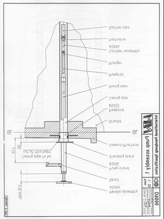
SKAT Design for Shallow Handpump-1
Source:
Malda Handpump Specifications, Revision 0-1997
For more details: SKAT, Vandianstrasse 42, CH-9000 St. Gallen, Switzerland, tel +41 712285454
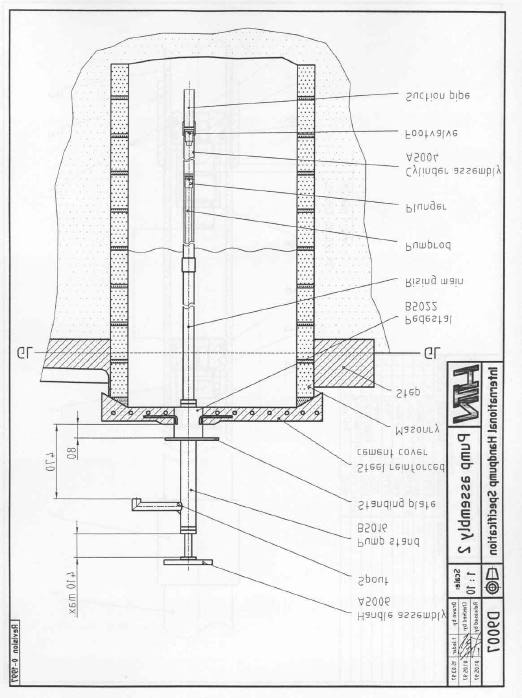
SKAT Design for Shallow Handpump-2
Source:
Malda Handpump Specifications, Revision 0-1997
For more details: SKAT, Vandianstrasse 42, CH-9000 St. Gallen, Switzerland, tel +41 712285454
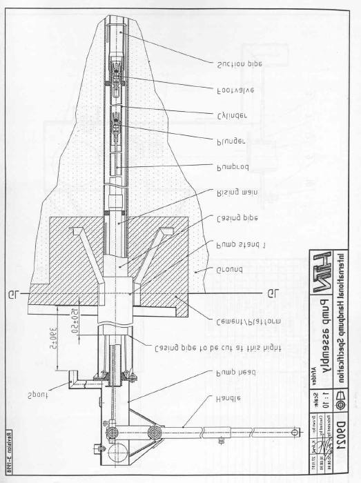
SKAT Design for Deep Handpump
(Afridev)
Source:
Afridev Handpump Specifications, Revision 3-1998
For more details: SKAT, Vandianstrasse 42, CH-9000 St. Gallen, Switzerland, tel +41 712285454
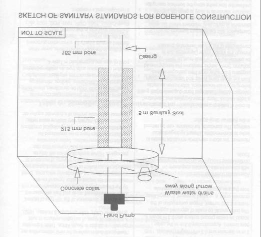
Design of Sanitary Sealing
Source : Xu, Y, Braune, E,; 1995; A Guide for Groundwater Protection for the Community Water Supply and
Sanitation Programme; DWAF; ISBN 0-621-16787-8, Republic of South Africa.
Available From : Department of Water Affairs, Pretoria, Republic of South Africa
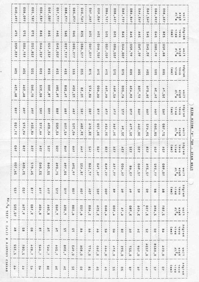
INTERNATIONAL DRINKING WATER QUALITY STANDARDS
(with special reference to groundwater sources)
EU Directive
W.H.O.
R.S.A. SABS
R.S.A. SABS
Parameter
Unit
98/83/EC
Guidelines, 19861
1984 (Max.)
1984 (Rec.)2
Colour
mg/l Pt-Co
Subjective criteria
15
-
20
Turbidity
N.T.U.
1
5
5
1
Taste
Subjective criteria
-
-
-
Odour
T.O.N.
Subjective criteria
5
-
-
pH
-log[H+]
6.5 - 9.5
6.5 - 8.5
5.5 - 9.5
6.0 - 9.0
Chloride, Cl
mg/l
250
250
600
250
Sulphate, SO4
mg/l
250
250
600
200
Sodium, Na
mg/l
200
200
400
100
Aluminium, Al
mg/l
0.2
0.2
-
0.15
Hardness, Total
mg/l
-
-
650
-
Solids, Total Dissolved TDS
mg/l
-
1,000
-
450
Conductivity (at 20oC)
ms/cm
2,500
-
3,000
700
Oxygen, dissolved
% saturation
75% min.5
-
-
-
CO , free
2
mg/l
-
-
-
-
Oxydisability, test by KMnO
mg/l as O
4
2
5
-
-
-
Nitrate, NO3
mg/l
50
50
44
27
Nitrite, NO2
mg/l
0.5
0.91
-
-
Ammonium, NH4
mg/l
0.5
1.5
-
-
Hydrogen Sulphide, H S
2
mg/l
0.05
-
-
Benzene
mg/l
1
-
-
-
Pesticides, total
mg/l
0.5
-
-
-
Policyclic Aromatic Hydrocarbons
mg/l
0.1
-
-
-
Boron, B
mg/l
1,000
300
-
-
Iron, Fe
mg/l
200
300
1,000
100
Manganese, Mn
mg/l
50
500
1,000
50
Copper, Cu
mg/l
2,000
2,000
1,000
500
Zinc, Zn
mg/l
3,000
5,000
1,000
Fluoride, F
mg/l
1,500
1,500
1,500
1,000
Antimony, Sb
mg/l
5
5
Arsenic, As
mg/l
10
10
300
100
Barium, B
mg/l
700
Cadmium, Cd
mg/l
5
3
20
10
Chromium, Cr
mg/l
50
50
Cyanide, CN
mg/l
50
70
300
200
Lead, Pb
mg/l
10
10
100
50
Mercury, Hg
mg/l
1
1
10
5
Nickel, Ni
mg/l
20
Selenium, Se
mg/l
10
10
50
20
Total Coliforms3
MPN/100 ml
0
04
5
0
Faecal Coliforms3
MPN/100 ml
0
0
0
0
Notes:
1. Recommended maximum allowable value for parameter (W.H.O. Guidelines for Developing Countries)
2. Parameter values supplemented by values from DWAF Guidelines (RSA) where not available in SABS 1984
3. After disinfection (as measured in distribution system). Please consult WHO Guidelines for classification of Raw Water quality
4. Not less than 95% of distribution samples to be clear on a monthly basis
5. Does not apply to groundwater. Groundwater should be aerated before use.
EXISTING INSTITUTES WITHIN THE SADC REGION PROVIDING
DEGREES IN HYDROGEOLOGY
1. Institute of Groundwater Studies (IGS) associated with University of Free State in
Bloemfontein Ł Post-graduate degree in Hydrogeology
2. Rhodes University (South Africa)- Graduate courses in Hydrogeology
3. Witwatersrand (South Africa)- Graduate courses in Hydrogeology
4. Pretoria Technicon (South Africa)- 3-year course in Geotechnologies mostly
oriented towards mining, but with some focus on groundwater aspects in the third.
A fourth year has been added as an advanced course in Geotechnology.
5. University of Venda (South Africa)- A course is being established on
Hydrogeology
6. University of Western Cape (South Africa)- Degree level course is under
development supported by UNESCO funding, on community based
Geohydrology, with basic idea of linking social and technical aspects.
7. University of Botswana - Course in Hydrogeology as part of geology degree.
Master programme in Hydrogeology to begin in2001. Short courses are presented
regularly through the University.
8. University of Dar-es-Salam (Tanzania) - Course in Hydrogeology as part of
geology degree; Post graduate degree in Water Resource Engineering and;
Environmental Engineering with significant hydrogeology component
9. University Eduardo Mondlane (Mozambique); Department of Geology: 64-hour
subject on Hydrogeology; Civil Engineering Department: 96-hour subject on
Hydrogeology, with some emphasis on Mathematical aspects of goundwater
movement
10. Agostinho Neto University (Angola); Department of Geology (DG): 5 year course
in Geology, 0.5 years optional, one of the courses being Applied Geology,
including Geophysical Methods, Hydrochemistry, Advanced Computation, Water
Resources Management, Surface Hydrology, and Field Work
11. University of Zimbabwe - The Geology degree includes Hydrogeology courses
and Honors students may purse Hydrogeology topics for their researches; The
Civil Engineering Department offers an M.Sc Programme with a Hydrogeology
component.
EXISTING TRAINING FOR TECHNICIANS
Rwegarulila Water Resources Institutes (RWRI) in Tanzania; Curriculum covers
wide spectrum of groundwater related topics, including Geology, Grilling and
Horehole Construction Technology, Hydrogeology Groundwater Modelling,
Geophysics Shallow Wells Technology, Pump/Lifting Devices, Water Analysis and
Computer Sciences.
ON THE JOB AND SHORT COURSES TRAINING PROGRAMME
- Groundwater divisions in Governments,
- Private sector: important role in particular to provide on-the-job training
for own personnel (mainly at technician level) and for counterparts in
major projects supervised government,
- Drilling Contractors Association of South Africa has a 3 year training
manual to cover various drilling activities,
- REGIDESO (DRC) has two training centres, one in Kinshasa, and one in
Lubumbash.i. Teaching modules for groundwater development procedures,
methods and techniques are used in training,
- Groundwater Association of Botswana,
- Groundwater division of the geological Society of South Africa
(Courses and confertences)
LIST OF USEFUL SOFTWARE
Software Name
Purpose
Available From
Author
WebSite
Integrated Graphical Simulation
Institute for Groundwater Wen-Hsing
System for 3 D Modelling using
Studies, P O Box 339,
Chiang and
Processing Modflow for
MODFLOW, MT3D, MT3DMS,
Bloemfontein 9300, South Wolfgang
www.uovs.ac.za/faculties/igs/so
Windows (Ver 5.1)
MOC3D, PMPATH 98
Africa
Kinzelbach
ftware.htm
Waterloo Hydrogeologic,
180 Columbia Street
West- Unit 1104,
Visual Modflow
3 D modelling software
Waterloo, Ontario, Canada -
www.flowpath.com
Institute for Groundwater
Studies, P O Box 339,
For 2 D finite element groundwater
Bloemfontein 9300, South G van Tonder and www.uovs.ac.za/faculties/igs/so
AQUAWIN and NETGEN modelling
Africa
Eelco Lukas
ftware.htm
Institute for Groundwater
Studies, P O Box 339,
An MS Excel code for groundwater
Bloemfontein 9300, South G van Tonder and www.uovs.ac.za/faculties/igs/so
Recharge Estimate
recharge estimate
Africa
Yongxin Xu
ftware.htm
Institute for Groundwater
Studies, P O Box 339,
An MS Excel code for calculation for Bloemfontein 9300, South
www.uovs.ac.za/faculties/igs/so
FC-Method
sustainable yield of borehole.
Africa
G van Tonder
ftware.htm
Institute for Groundwater
GUI for hydrogeologists to draw maps, Studies, P O Box 339,
access data sets and perform various
Bloemfontein 9300, South Eelco Lukas and www.uovs.ac.za/faculties/igs/so
WISH
analysis.
Africa
Frank Hodgson
ftware.htm
Hydrosolve Inc., 2303
Horseferryu Court,
AQTESOLV
Pump test analysis
Reston, VA, USA
-
www.aqtesolv.com
The Scientific Software
Analysis of Step Drawdown pump test Group, P O Box 23041,
StepMaster
data
Washington, USA
-
www.scisoftware.com
Groundwater Consultants,
Analysis of Step Drawdown pump test P O Box 7885, Maseru
Step Test v2
data
100 Lesotho
S K Pandey
www.ilesotho.com/mpandey/step
The Scientific Software
Group, P O Box 23041,
PLOTCHEM
Water quality data plotting software
Washington, USA
-
www.scisoftware.com
The Scientific Software
QuickLog/QuickCross/
Plotting of borehole logs, cross
Group, P O Box 23041,
QuickFence
sections and fence diagrams
Washington, USA
-
www.scisoftware.com

GROUNDWATER CONSULTANTS Bee Pee (Pty) Ltd.
P.O. Box 7885
243 Manong Road (c/o Koekoe)
Maseru 100
Hillsview
Lesotho
Maseru
Phone/Telefax : +266 311 227 / 326 461
e-mail: bakaya @lesoff.co.za
Document Outline
- November 2001
- Cover Page-Inside-ian.pdf
- Sep-Main Report.pdf
- Main Report -Final-ian.pdf
- Sep-Appendices.pdf
- Cover-Appendix A.pdf
- 1 - Appendix A-1 References.pdf
- A-2 - Reports.pdf
- Cover-Appendix A.pdf
- Sep-Appendices.pdf
- Sep-Appendices.pdf
- Cover-Appendix B.pdf
- B- List of Contents.pdf
- C- List of Contents.pdf
- Back Cover Page-ian.pdf