CSIR REPORT ENV-S-C 99057
BENGUELA CURRENT LARGE MARINE ECOSYSTEM
THEMATIC REPORT NO. 4
Integrated Overview of the Offshore
Oil and Gas Industry in the
Benguela Current Region
October 1999
CSIR REPORT ENV-S-C 99057
BENGUELA CURRENT LARGE
MARINE ECOSYSTEM
THEMATIC REPORT NO. 4
Integrated Overview of the Offshore
Oil and Gas Industry in the
Benguela Current Region
Submitted to:
THE UNITED NATIONS DEVELOPMENT PROGRAMME
Co-ordinated by:
P D MORANT
CSIR, ENVIRONMENTEK
P O Box 320
Stellenbosch 7599
South Africa
Keywords:
Angola
Namibia
South Africa
Petroleum exploration
Petroleum production
Geology
Environmental impact assessment
Coastal
Offshore
Geophysical surveys
Exploration Drilling
October 1999
SCOPE
The Benguela Current Large Marine Ecosystem (BCLME) Thematic Report No. 4:
Integrated Overview of the offshore Oil and Gas Industry in the Benguela Current Region
was prepared as one of five reports serving as background for the Transboundary
Diagnostic Analysis phase of the BCLME proposal.
The study covers:
· History of oil and gas exploration and production in the BCLME area,
· Geology of the areas with petroleum potential,
· Exploration methods (geophysical and drilling),
· Potential environmental impacts and mitigation measures,
· Oil spill response,
· Legislation,
· Issues and conflicts,
· Information gaps.
The study team comprised:
ANGOLA:
Helena de Conceiçâo dos Santos André, Environmental Protection
Department, Ministry of Petroleum.
Luís Filipe Anapaz, Environmental Health and Safety Engineer, Texaco
Panama Inc., Angola.
Matias Felicoana Junior, SONANGOL.
NAMIBIA:
Dr Roy McG Miller, Consultant Geologist.
Dr Mick O'Toole, Ministry of Fisheries and Marine Resources.
SOUTH AFRICA:
Dr Ian R McLachlan, SOEKOR (Southern Oil Exploration
Corporation).
Patrick Morant, Environmentek, CSIR (Council for Scientific and
Industrial Research) - Project Co-ordinator.
REVIEWER Ger Kegge, Oil Exploration Consultant, Windhoek, Namibia.
CONTENTS
CHAPTER 1:
INTRODUCTION
1.1 Objectives of the Study.......................................................................................... 1.1
1.2 Study
Area ............................................................................................................. 1.1
CHAPTER 2:
HISTORY OF OIL AND GAS EXPLORATION AND
PRODUCTION
CHAPTER 3:
GEOLOGY
CHAPTER 4:
SEISMIC SURVEY TECHNIQUES
4.1 Introduction ........................................................................................................... 4.1
4.2 Environmental effects of seismic surveys ............................................................. 4.2
CHAPTER 5:
EXPLORATION DRILLING
5.1 Introduction ........................................................................................................... 5.3
5.2 Pre-drilling site surveys ......................................................................................... 5.4
5.3 The drilling operation ............................................................................................ 5.4
5.4 Well
testing............................................................................................................ 5.6
5.5 Plugging and abandonment of exploration wells................................................... 5.6
5.6 The
drilling
mud .................................................................................................... 5.6
5.7 Cement................................................................................................................... 5.8
CHAPTER 6:
ENVIRONMENTAL ASPECTS OF DRILLING
6.1 Introduction ........................................................................................................... 6.1
6.2 Cuttings.................................................................................................................. 6.1
6.3 Drilling
mud .......................................................................................................... 6.2
6.4 Other discharges into the sea ................................................................................. 6.4
6.5 Solid
waste............................................................................................................. 6.6
6.6 Atmospheric
emissions.......................................................................................... 6.7
CHAPTER 7:
OIL SPILLS AND CONTINGENCY PLANS
7.1 Contingency
plans ................................................................................................. 7.1
7.2 Oil
Spills.............................................................................................................. 7.10
CHAPTER 8:
LEGISLATION AND POLICY
8.1 Draft Decree on Environmental Protection for the Petroleum Industry ........page 8.2
CHAPTER 9:
INTERNATIONAL CONVENTIONS AND
ENVIRONMENTAL LAW
CHAPTER 10:
ENVIRONMENTAL ISSUES ARISING FROM OFFSHORE
OIL AND GAS EXPLORATION AND PRODUCTION
CHAPTER 11:
INFORMATION GAPS
REFERENCES
CHAPTER 1:
INTRODUCTION
Contents
1. INTRODUCTION ........................................................................................... 1.1
1.1
Objectives of the Study ............................................................................................................... 1.1
1.2 Study
Area .................................................................................................................................. 1.1
CHAPTER 1 : INTRODUCTION
1. INTRODUCTION
1.1 Objectives of the Study
This study aims to provide an overview of the offshore oil and gas industry in the Benguela Current region.
The study covers the history of oil and gas exploration and production activities, the areas of interest,
exploration methods, potential environmental impacts and mitigation measures, oil spill response and
legislation. The study draws on existing, available information and identifies gaps in information and
issues which could be addressed by the BCLME.
1.2 Study Area
The study area extends from the Cabinda Enclave north of the Congo River to the western half of the
Agulhas Bank (longitude 21°E) on the south coast of South Africa (Figure 1.1).
BCLME THEMATIC REPORT NO 4
Integrated Overview of the Offshore Oil and Gas Industry in the Benguela Current Region
page 1.1
CHAPTER 1 : INTRODUCTION
Figure 1.1:
The BCLME study area: the southwestern coast of Africa between
the Congo River mouth and Cape Agulhas
BCLME THEMATIC REPORT NO 4
Integrated Overview of the Offshore Oil and Gas Industry in the Benguela Current Region
page 1.2
CHAPTER 2:
HISTORY OF OIL AND GAS
EXPLORATION AND PRODUCTION
Contents
2. HISTORY OF OIL AND GAS EXPLORATION AND PRODUCTION . 2.1
Figures
Figure 2.1: Petroleum lease blocks on the Angolan continental shelf............................................................... 2.3
Figure 2.2: Namibia: petroleum exploration licence blocks and location of exploration wells ....................... 2.5
Figure 2.3: Namibia: location of non-exclusive offshore seismic surveys....................................................... 2.9
Figure 2.4: South Africa: Offshore licence blocks, participation blocks and mining leases ........................... 2.11
Figure 2.5: South Africa: licence areas in the BCLME study petroleum exploration area ............................ 2.13
Figure 2.6: South African offshore petroleum exploration: multi-channel seismic coverage ......................... 2.14
Figure 2.7: South Africa: Exploration wells drilled off the West-coast .......................................................... 2.15
Figure 2.8: Organisation of the South African Petroleum upstream sector..................................................... 2.16
Figure 2.9: South Africa: aims and key members of the Agulhas Bank and West Coast Liaison Committee 2.18
Figure 2.10: Offshore Petroleum Association of South Africa: Objectives and Activities ............................... 2.19
Tables
Table 2.1: Petroleum exploration licences issued in Namibia since 1992 ....................................................... 2.6
Table 2.2: Namibia: post-1989 non-exclusive seismic surveys acquired for, or on behalf of, NAMCOR ..... 2.7
Table 2.3: South African West Coast Petroleum Exploration Licences (As at June 1999) ........................... 2.17
CHAPTER 2 : HISTORY OF OIL AND GA S EXPLORATION A N D PRODU CTION
2.
HISTORY OF OIL AND GAS
EXPLORATION AND
PRODUCTION
ANGOLA
The following description of the history of oil exploration and production in Angola is taken from Africa
south of the Sahara 1998 (27th Ed.) produced by Europa Publications, London.
In 1955 a Belgian-based company, Petrofina, discovered petroleum in the Cuanza valley. A petroleum
company, Fina Petróleos de Angola (PETRANGOL), was subsequently established, under the joint
ownership of the Angola government and Petrofina interests. PETRANGOL constructed a refinery in the
suburbs of Luanda. The greatest impetus to expansion came from the Cabinda Gulf Oil Co (Cabgoc),
which discovered petroleum offshore at Cabinda in 1966. In 1976 a national oil company, the Sociedade
Nacional de Combustíveis de Angola (SONANGOL), was established to manage all fuel production and
distribution. In 1978 SONANGOL was authorized to acquire a 51% interest in all petroleum companies
operating in Angola, although the management of operations was to remain under the control of foreign
companies. In the late 1970s the government initiated a campaign to attract foreign oil companies. In
1978-79 SONANGOL divided the Angolan coast, excluding Cabinda, into 13 exploration blocks, which
were leased to foreign companies under production-sharing agreements. Although Cabgoc's Cabinda
offshore fields (which are operated by the US Chevron Corpn) remain the core of the Angolan petroleum
industry (accounting for about two-thirds of total output), production is buoyant at other concessions, held
by Agip, Elf Aquitaine, Conoco and Texaco. In addition SONANGOL itself operates a production block in
associated with Petrobrás Internacional (BRASPETRO) of Brazil and Petrofina. In 1992 Elf took a 10%
interest in Cabgoc, reducing SONANGOL's share to 41%, with Chevron holding 39.2% and Agip 9.8%.
Onshore, Petrofina remained the operator. SONANGOL took a 51% interest in Petrofina's original Cuanza
valley operations, including the Luanda refinery, whose capacity meets most domestic requirements.
SONANGOL also had a 51% interest in an onshore venture by Petrofina in the River Congo estuary area,
in which Texaco held a 16.33% share. Onshore production in 1991 was estimated at 30,000 b/d; however,
with recoverable petroleum reserves almost exhausted and activities vulnerable to UNITA attack,
production declined and in 1993 Petrofina suspended onshore operations near the port of Soyo, in northern
Angola near the Zaire border. Production was resumed, however, in February 1996, and an output of 5,000
b/d was quickly restored. It was forecast that production would advance to 12,000 b/d by early 1997.
BCLME THEMATIC REPORT NO 4
Integrated Overview of the Offshore Oil and Gas Industry in the Benguela Current Region
page 2.1
CHAPTER 2 : HISTORY OF OIL AND GA S EXPLORATION A N D PRODU CTION
Despite the uncertain security situation in the Cabinda enclave, exploration licences for three onshore
blocks were awarded in October 1992. The principal operators for the three concessions, Cabinda North,
Central and South, were to be Occidental of the USA, British Petroleum and Petrofina respectively. In
1994 Chevron announced the discovery of four new offshore fields. It estimated that production would
increase from 320,000 b/d in 1994 to 390,000 b/d in 1995 as the development of deep-water areas
continued under its five-year programme. In 1995 Chevron announced a US $5,100 m capital and
exploration expenditure programme for that year, an increase of 5% on 1994. In 1997 Chevron announced
its intention to invest $700 m a year until 2000 and envisaged increasing its output to 600,000 b/d. In late
1994 Texaco announced a five-year investment programme for petroleum exploration and production
totalling $600 m; the programme aimed to increase Texaco's output in the country by 50%. In September
1996 SONANGOL signed new production sharing agreements with six international petroleum companies:
Shell Exploration Angola, Amoco Angola, Eagle (Nigeria), Petro Inett Corpn (South Africa), Mobil and
Texaco.
Output of petroleum expanded rapidly during the 1980s, reflecting continued investment in the sector. it
was estimated that total investment in Angola by oil companies for the period 1987-90 would reach US
$2,050 m. Total Angolan production averaged 155,00 b/d in late 1982, rising to about 285,000 b/d in 1986,
to 358,000 b/d in 1987 and to 450,000 b/d in 1988 and 1989. Output rose to 475,000 b/d in 1990, 490,000
b/d in 1991, and 549,000 b/d in 1992. Following a small decline in 1993, production increased
consistently, reaching an estimated 750,000 b/d in 1997. Output was projected to increase to 780,000 b/d
by 1998, of which 450,000 b/d would be produced by Chevron in Cabinda's offshore fields alone, and to 1
m b/d by 2000. In April 1997 Chevron announced the discovery of a further new oil field of the coast of
Cabinda which was thought capable of producing an additional 20,000 b/d. In May, following another
significant deep-water discovery, production began in the remote North N'Dola oil field, which was
expected to yield up to 20,000 b/d by the end of 1997. In August Elf Aquitane announced the discovery of
one of Africa's largest ever petroleum field, with estimated reserves of 3,500 m barrels, off the Angolan
coast. In that year the law governing the exploitation of petroleum was under revision with a view to
facilitating further foreign investment. Petroleum production appeared to be relatively unaffected by the
resumption of hostilities in late 1992, and the main installations in Cabinda escaped attack by UNITA or the
regional separatist organization, FLEC. Before withdrawing from Soyo in late 1994 UNITA destroyed the
onshore installations. However, in March 1995 the government announced that production would resume,
although at a reduced rate of 5,000 b/d.
The major portion of Angola's petroleum is exported to the USA in its crude form (397,000 b/d during
1997), although the 30-year-old Luanda refinery processes around six tons of crude petroleum per day. The
government announced in April 1998 that it intended to invest US $10 m to upgrade and increase the
capacity of the Luanda refinery. There are also plans to construct a new refinery, with financial support
from the People's Republic of China, at Lobito. The new refinery, which was expected to be completed by
2003, was to cost some $1,000 m and would be capable of processing 200,000 b/d.
BCLME THEMATIC REPORT NO 4
Integrated Overview of the Offshore Oil and Gas Industry in the Benguela Current Region
page 2.2
CHAPTER 2 : HISTORY OF OIL AND GA S EXPLORATION A N D PRODU CTION
Figure 2.1:
Petroleum lease blocks on the Angolan continental shelf
Angola's export earnings from petroleum increased after 1982, following the rise in production, and
reached US $1,191 m in 1985. With the sharp fall in the price of petroleum, export earnings declined to
$1,140 m in the following year, but recovered to $2,100 m in 1987, $2,250 m in 1988, $2,700 m in 1989
BCLME THEMATIC REPORT NO 4
Integrated Overview of the Offshore Oil and Gas Industry in the Benguela Current Region
page 2.3
CHAPTER 2 : HISTORY OF OIL AND GA S EXPLORATION A N D PRODU CTION
and - helped by increased production and a period of higher prices, due to the Gulf crisis - an estimated
$3,250 m in 1990. In 1991 petroleum export earnings stood at $3,217 m, increasing to $3,556 m in 1992
before declining to $2,813 m in 1993. In 1995 estimated earnings from petroleum exports stood at $5,000
m. As Angola is not a member of OPEC, the country is not constrained by production quotas, enabling it to
stabilize the value of its petroleum exports during the late 1980s, when world prices remained depressed, by
increasing output.
The entire Angolan continental shelf has been divided into Lease Blocks (Figure 2.1). At present interest
has been focussed on the northern continental shelf although exploration (geophysical surveys) is now
taking place as far south as Lobito (Lease Block 25).
NAMIBIA
In the 1960s, South Africa, which was administering the then South West Africa, made a concerted effort to
encourage petroleum exploration. This was administered by SWAKOR, the predecessor of the National
Petroleum Corporation of Namibia (NAMCOR), and SOEKOR, the South African equivalent of
SWAKOR. Seismic surveying offshore Namibia began in 1968. By 1974 the whole offshore was covered
by licences. Although concentrated on the continental shelf down to 200 m, some seismic surveys extended
as far as 250 km offshore along the Walvis Ridge and down to water depths of 1 500 m. A total of 37 219
km of 2-D seismic data was acquired up to 1978 but only one well was drilled. This was the Kudu 9A-l
well drilled by Chevron, Regent and SOEKOR in 1974 which discovered the Kudu gas field some 170 km
due west of Oranjemund in water 170 m deep.
During this same period, the deep-sea drilling programme (DSDP) drilled four wells in deep water on or
near the Walvis Ridge. These were important for understanding the Namibian offshore geology and its
petroleum potential.
With the intention of investigating the Kudu gas discovery further, SWAKOR acquired 239 km of 2D
seismic data in 1985 around the Kudu 9A-1 well. It then drilled the Kudu 9A-2 well in 1987 and the Kudu
9A-3 well in 1988. Kudu 9A-2 encountered gas in the main reservoir sandstone but on the advice of
consultants this was not tested. The highly successful Kudu 9A-3 well, which flowed at a rate of 38 million
cubic feet of gas per day, proved that the size of the Kudu gas reservoir is significant.
A potential reserve of at least 5 trillion cubic feet (TCF) of gas was estimated. This is still the largest
reserve of natural gas south of Angola. It also proved that the reservoir sandstone covers a large area, that
source rocks are present, that the volumes of gas present are large enough to be of commercial interest and
that the southwestern offshore region of Africa could well be a petroleum province (Miller, 1998b).
BCLME THEMATIC REPORT NO 4
Integrated Overview of the Offshore Oil and Gas Industry in the Benguela Current Region
page 2.4
CHAPTER 2 : HISTORY OF OIL AND GA S EXPLORATION A N D PRODU CTION
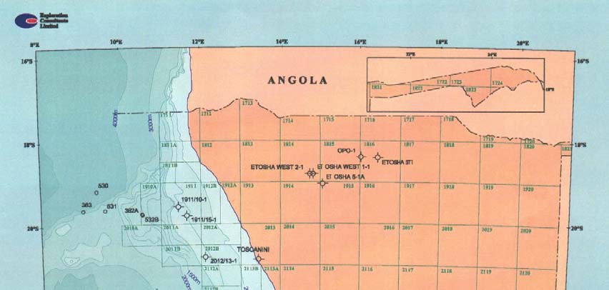
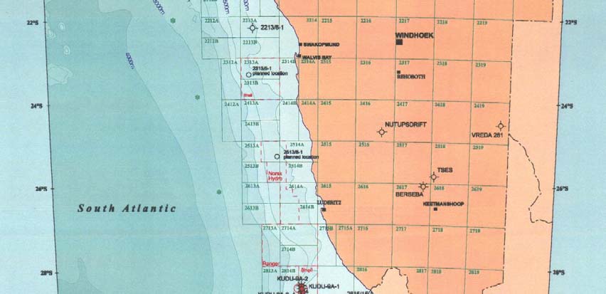
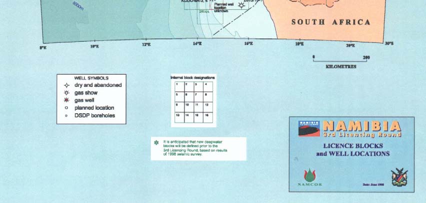
Figure 2.2:
Namibia: petroleum exploration licence blocks and location of exploration wells
BCLME THEMATIC REPORT NO 4
Integrated Overview of the Offshore Oil and Gas Industry in the Benguela Current Region
page 2.5
CHAPTER 2 : HISTORY OF OIL AND GA S EXPLORATION A N D PRODU CTION
Compilation of up-to-date, progressive, straightforward yet comprehensive and strict petroleum legislation
began just prior to Namibia's independence with assistance from consultants, the Government of the
Kingdom of Norway and the Commonwealth Secretariat.
Namibia's first petroleum licensing round opened in 1991 and attracted 19 bids for 14 licence areas each
covering approximately 11 000 km2. Up to six bids were received for specific areas. The first exploration
licence was awarded by the Government of the Republic of Namibia in April 1992 to a consortium of
Norwegian companies headed by Norsk Hydro Namibia. Shell Exploration and Production Namibia
(SEPN) and its partner Eagle Energy (now Energy Africa) were awarded a licence over the Kudu gas field.
Texaco joined that consortium in 1996. The second licensing round was held in 1994/95. The third opened
on 1 October 1998 and will close on 31 March 1999. Third round licences are expected to be awarded
during the year 2000. Table 2.1 lists the licences issued during the first and second licensing rounds, the
renegotiated licences, the partners in each licence, the seismic data acquired and the wells drilled. Figure
2.2 shows the location of the wells.
All licences awarded so far have been for offshore areas within the Namibian Exclusive Economic Zone.
Since the award of the first licence, over 28 000 km of new 2-D seismic data and 700 km of 3-D seismic
data (the first in Namibia) have been acquired, processed and interpreted by exploration companies and the
data lodged with NAMCOR. In addition, eight widely spaced wells, some up to 4 500 m deep, have been
drilled between 40 and 120 km offshore in water depths ranging from 170 m to almost 700 m.
Table 2.1:
Petroleum exploration licences issued in Namibia since 1992
TOTAL
AEROM
TOTAL
WELLS
AG-
LICEN
SEISMIC
LICENCE
DRILLED; NETIC
STATUS OF
CE
OPERATOR PARTNERS ACQUIRE
AREA
TOTAL
SURVEY
LICENCE
NO
D
DEPTH
S
(km)
(m)
(km)
First Round Licences
001 1911 Norsk
Hydro Statoil, Saga 2D B 8010 1911/15-1 B 32 500
Relinquished
Namibia
Petroleum
4564m
1911/10-1
- 4185m
002 2213N Ranger
Oil Hardy Oil & 2D - 2300 2213/6-1
Relinquished
Namibia
Gas,
B 2605m
Amarada
Hess
003
2012
Sasol Petroleum
2D - 5889 2012/13-1 28 340
Relinquished
B 3699m
004 2815 Chevron
Energy
2D - 3244 2815/15-1 Relinquished
Overseas
Africa, Shell
B 4750m
Namibia
Namibia
BCLME THEMATIC REPORT NO 4
Integrated Overview of the Offshore Oil and Gas Industry in the Benguela Current Region
page 2.6
CHAPTER 2 : HISTORY OF OIL AND GA S EXPLORATION A N D PRODU CTION
TOTAL
AEROM
TOTAL
WELLS
AG-
LICEN
SEISMIC
LICENCE
DRILLED; NETIC
STATUS OF
CE
OPERATOR PARTNERS ACQUIRE
AREA
TOTAL
SURVEY
LICENCE
NO
D
DEPTH
S
(km)
(m)
(km)
Exploration
005 2814A Shell
Energy
2D B 2095 Kudu 4 -
Whole
enlarged
(Blocks
Exploration and Africa,
3D B
4705 m
licence area
3,4,7,8,
Production
Texaco
700km2
Kudu 5 B
declared a
11,12)
Namibia
4898 m
petroleum field
Renegotiated First Round Licences
006 2713A, Ranger Oil
Hardy Oil & 2D - 3000
Relinquished
2714
Namibia
Gas,
Amarada
Hess
008 Parts
of Norsk Hydro
Statoil, Saga 2D - 1400 2513/6-1 - < To
be
2513, 2514, Namibia
Petroleum
3000m
relinquished end
2614
1998
Second Round Licences
007 2313 Shell
Namibia
2D
B 2500
Still current
Exploration
005
Blocks 15 and 16 of area 2814 added to Licence 005
Since 1989, NAMCOR, through various agents, has acquired 19 500 km of 2-D non-exclusive seismic data
which has been used to promote the potential of the Namibian offshore and to attract investment. Figure
2.3 shows the location of the various non-exclusive seismic surveys listed in Table 2.2.
Table 2.2:
Namibia: post-1989 non-exclusive seismic surveys acquired for, or on behalf of,
NAMCOR
TOTAL
LENGTH OF
SURVEY
YEAR
SURVEY LINES
(km)
HGS/ECL 1989 Regional seismic survey, Namibia (marketed by
1989 10
002
GeoQuest)
HGS/ECL 1991 Regional seismic survey, Namibia (Namibe and
1991 3
774
Walvis Basins) (marketed by GeoQuest)
NAMCOR 1992 seismic survey, Walvis Basin (marketed by NOPEC)
1992
1 165
NOPEC 1993 seismic survey, Namibe and Walvis Basins
1993
10 077
NAMCOR 1995 seismic survey, Lüderitz Basin (marketed by
1995 1
950
GeoQuest)
Western Geophysical 1997 seismic survey, Namibe Basin
1997
1 217
NAMCOR/GECO 1997 Orange Basin seismic survey, (west and south
1997
1 036
BCLME THEMATIC REPORT NO 4
Integrated Overview of the Offshore Oil and Gas Industry in the Benguela Current Region
page 2.7
CHAPTER 2 : HISTORY OF OIL AND GA S EXPLORATION A N D PRODU CTION
TOTAL
LENGTH OF
SURVEY
YEAR
SURVEY LINES
(km)
Kudu)(marketed by GeoQuest)
Western Geophysical 1998 deep-water survey, Walvis and Lüderitz
1998 5
117
Basins
Investment in petroleum exploration in Namibia since 1989
The total investment by exploration licence holders on environmental impact assessments, training of
Namibians, contributions to the Petroleum Education and Training Fund, seismic acquisition and drilling of
wells has been approximately N$ 580 million since independence. The Government and NAMCOR,
together with NORAD and private seismic companies have also spent considerable amounts on
internationally promoting petroleum exploration in Namibia, on the administration of exploration activities
and on training Namibians to understand and administer the upstream petroleum industry. The largest
contributor since 1990 in this regard outside the private sector has been NORAD which provided N$ 37
million. In the same period, Government contributed N$ 6.8 million and NAMCOR spent N$ 11.2 million
of its own funds. Seismic acquisition companies, recognising the potential for significant sales of seismic
data, spent the equivalent of N$ 88 million of their own money in acquiring non-exclusive seismic data
under contract to NAMCOR.
Areas of interest
Figure 2.2 shows the licence areas on offer in Namibia's 3rd Licencing Round. Although these areas
extend to the onshore, the known offshore geology strongly suggests that petroleum exploration south of
the Walvis Ridge, where the continental shelf is approximately 100 km wide, is only likely to take place
beyond about 40 km from shore and that most of this exploration will be in water depths of between 150 m
and 1 500 m, i.e. between about 70 and 180 km offshore. This assumption is based on the fact the parts of
the Namibian stratigraphic succession in the deeper offshore has many similarities to the West African
deep-water geological succession where several huge discoveries have been made in the past few years in
water depths of up to 1 400 m. The Kudu gas field occurs in water depths of 170 m. The 1998 seismic
survey acquired by Western Geophysical recorded to water depths of 3 500 m to allow proper coverage and
therefore proper interpretation and evaluation of geological structures at slightly shallower water depths
(Shell has been drilling exploration wells in water depths of 2 400 m in the Gulf of Mexico).
In the Namibe Basin exploration may well take place closer to shore since the continental shelf here is only
about 35 km wide and geology below the shelf and the continental rise as it extends into deeper water has
many interesting structures. The 2 000 m isobath is approximately 70 km offshore.
BCLME THEMATIC REPORT NO 4
Integrated Overview of the Offshore Oil and Gas Industry in the Benguela Current Region
page 2.8
CHAPTER 2 : HISTORY OF OIL AND GA S EXPLORATION A N D PRODU CTION
Figure 2.3:
Namibia: location of non-exclusive offshore seismic surveys
BCLME THEMATIC REPORT NO 4
Integrated Overview of the Offshore Oil and Gas Industry in the Benguela Current Region
page 2.9
CHAPTER 2 : HISTORY OF OIL AND GA S EXPLORATION A N D PRODU CTION
SOUTH AFRICA
The following description of the history of oil and gas exploration in South African waters has been
compiled from Graham et al. (1997) and Van Vuuren et al. (1998) and information provided by the
SOEKOR Petroleum Licencing Unit.
In 1951 Dr Franz Quass, a senior research officer of the Fuel Research Institute of South Africa, published
a report that contained two critical recommendations: that the then Union of South Africa commence an
organised oil search as soon as possible and that sufficient synthetic fuel plants be established to make the
country independent of imported oil supplies within 20 to 25 years (Quass, 1951). Almost 15 years were to
pass before the changing domestic and world scenario eventually gave new impetus to the idea of South
Africa's own oil search - and the formation of SOEKOR.
The Southern Oil Exploration Corporation (Pty) Ltd was registered on 12 January 1965. From the outset it
was known as "SOEKOR", but it was only in 1980 that this became its official name. SOEKOR was
charged with the responsibility of not only exploring for oil alone, but also of co-ordinating the efforts of
other companies and of actively encouraging exploration onshore and offshore.
SOEKOR was granted oil and gas exploration rights to all South African areas which had not already been
leased. These included various onshore areas under a number of different leases, the last of which was
Prospecting Lease OP 29 (which terminated in 1992) and most of the continental shelf under Prospecting
Lease OP 26. Originally OP 26 extended only to the 200 m water depth contour. In line with international
practice, it was subsequently extended to also cover the exclusive economic zone which extends out to sea
for 200 nautical miles from the shoreline.
Offshore, the international companies started off vigorously, competing for the 50% tax reduction promised
to the first discoverers of commercial oil and gas offshore. Aeromagnetic and seismic surveys were carried
out, and in 1969, Superior drilled the first well which discovered non-commercial quantities of gas, with
some condensate, off Plettenberg Bay. Other companies joined in the race: Placid Oil Company, Chevron,
Elf Aquitaine, the Total Consortium (in which Mobil and Shell had interests), the Odeco Consortium (in
which Sasol had an interest), and a Rand Mines consortium (in which SOEKOR had an interest). The next
gas strike was made by a Chevron/Regent/SOEKOR group in 1974, when they discovered the Kudu gas
field offshore Namibia. Among further discoveries made by SOEKOR in South African waters were the F-
A gas field, discovered in 1980 and the E-BT (ORIBI) oil field, discovered in 1990. The South Coast,
particularly the Bredasdorp Basin (Block 9), received the main focus of interest in following years when
wells were drilled to follow up on the early gas discoveries and the possibility of additional and hopefully
larger oil fields.
BCLME THEMATIC REPORT NO 4
Integrated Overview of the Offshore Oil and Gas Industry in the Benguela Current Region
page 2.10
CHAPTER 2 : HISTORY OF OIL AND GA S EXPLORATION A N D PRODU CTION
Figure 2.4:
South Africa: Offshore licence blocks, participation blocks and mining leases
BCLME THEMATIC REPORT NO 4
Integrated Overview of the Offshore Oil and Gas Industry in the Benguela Current Region
page 2.11
CHAPTER 2 : HISTORY OF OIL AND GA S EXPLORATION A N D PRODU CTION
A total of 194 exploration, 58 appraisal and nine production wells have been drilled off the South African
coast and 190 000 km of two-dimensional and 2 300 km2 of three-dimensional seismic data have been
acquired. Exploration has resulted in 20 gas and nine oil discoveries, all but two of which are located in the
Bredasdorp basin. The F-A gas field is presently in production and the E-BT (ORIBI) oil field commenced
production in 1998.
Some 30 wells have been drilled off the west coast of South Africa, i.e. in the BCLME study area
(Figure 2.5 and Figure 2.7).
Despite the early promise of the Kudu gas discovery, the pace of exploration on the West Coast has been
relatively slow. Of the companies that took up licences (Chevron, Elf Aquitaine, Esso and Amoco), only
Elf Aquitaine proceeded with drilling three wells. By the end of 1976, all foreign exploration companies
had left the area and SOEKOR carried on as sole explorer. By 1992, 48 000 km of 2D seismic data had
been acquired and 30 wells drilled on the South African West Coast, resulting in one oil and three gas
discoveries. More than half of the wells had gas shows.
In 1987, Energy Africa (formerly Engen), joined SOEKOR as a partner in the exploration for oil in the
Bredasdorp Basin (Block 9). This arrangement lasted until 1995 and during this time, a number of
potentially commercial oil and gas discoveries were made.
Another major development in 1987, was the decision by the government to proceed with the development
of the FA gas field. Mossgas was established as a separate company to manage the project, under the
Central Energy Fund and was awarded mining leases over the FA and EM gas fields. The decision was
taken to use a bottom supported platform to produce gas and condensate and to export both products to a
shore-based factory where the gas would be converted by a modified Fishcher Tropsch process (the Synthol
process) into petrol and diesel. Production started in 1992 and has been continued at a rate of about 183
million standard cubic feet of gas and 10 500 barrels of condensate per day.
By 1993, the winds of political change were blowing strongly as oil sanctions fell away and the government
of the day looked to withdraw from direct participation in the petroleum search. The pace of exploration
and associated funding was dramatically reduced and SOEKOR put in place a process of restructuring and
right-sizing.
A public licensing round was held in October 1994 (just 5 months after the national elections) to attract
international exploration companies. Despite selling a significant amount of data, no applications were
received. An independent consultant was appointed to establish the reasons for the negative response.
High on the list were uncompetitive tax rates and uncertainty about how the new government would
manage the economy, particularly the petroleum sector.
BCLME THEMATIC REPORT NO 4
Integrated Overview of the Offshore Oil and Gas Industry in the Benguela Current Region
page 2.12
CHAPTER 2 : HISTORY OF OIL AND GA S EXPLORATION A N D PRODU CTION
Figure 2.5:
South Africa: licence areas in the BCLME study petroleum exploration area
BCLME THEMATIC REPORT NO 4
Integrated Overview of the Offshore Oil and Gas Industry in the Benguela Current Region
page 2.13
CHAPTER 2 : HISTORY OF OIL AND GA S EXPLORATION A N D PRODU CTION
Figure 2.6:
South African offshore petroleum exploration: multi-channel seismic coverage
BCLME THEMATIC REPORT NO 4
Integrated Overview of the Offshore Oil and Gas Industry in the Benguela Current Region
page 2.14
CHAPTER 2 : HISTORY OF OIL AND GA S EXPLORATION A N D PRODU CTION
Figure 2.7:
South Africa: Exploration wells drilled off the West-coast
The restructuring of SOEKOR resulted in the establishment of three separate entities (see organogram).
SOEKOR PTY LTD (the holder of exploration lease OP26), SOEKOR E and P (a separately registered
subsidiary company, intended to become commercially independent) and the SOEKOR Petroleum
Licensing Unit (a division of SOEKOR PTY LTD). As part of this process, the exploration rights for
natural oil of two areas (Blocks 9 and 11a) in which potentially commercial discoveries had been made by
SOEKOR Pty Ltd were ceded (effective date October 1994) to SOEKOR E and P.
A powerful motivating factor in expediting the commercial independence of SOEKOR E and P was the
government decision to terminate all funding of the company by the end of 1995? To its credit, SOEKOR
E and P succeeded in bringing the Oribi (E-BT) oil field on stream in May 1997 and effectively became
self-funding from this date. Production averages 24 000 barrels of oil and 15 million standard cubic feet of
gas per day. The need to spread the costs and risks of exploration and development in Blocks 9 and 11a
was addressed by taking on board Pioneer Natural Resources and Petroleum Ltd as partners in 1998.
BCLME THEMATIC REPORT NO 4
Integrated Overview of the Offshore Oil and Gas Industry in the Benguela Current Region
page 2.15
CHAPTER 2 : HISTORY OF OIL AND GA S EXPLORATION A N D PRODU CTION
Figure 2.8:
Organisation of the South African Petroleum upstream sector
The Oribi project proved robust enough to survive the oil price crisis of 1998/1999 when crude prices
tumbled by some 30%. The company is now going ahead with bringing the Oryx (E-AR) oil field into
production by mid-2000 and tying it back to the Orca production platform on the adjacent Oribi oil field.
The possibility is being assessed of bringing the EBD/ECE oilfield into production by end-2000. The Orca
production facility is based on a converted semi-submersible drilling rig. Oil production is delivered to
shore with a single shuttle tanker. A major merit of the system is that it can be moved to a new location
when Oribi and its satellites are depleted, leaving the seafloor clean of obstructions.
In 1999, the decision was taken to cede to Mossgas Pty Ltd the gas rights to the area around the FA/EM gas
fields (basically the northeastern quarter of Block 9), to allow it to explore for gas to extend the life of the
FA platform. The development of the EM gas field was also given the go-ahead. Gas and condensate will
be exported by 48 km twin pipelines to the FA platform and then to shore in the existing FA pipelines.
After the unpromising start with the un-productive licensing round in 1994, it was decided that a dedicated
petroleum licensing unit should be created to focus on the task of marketing the offshore acreage to
international explorers. The SOEKOR PLU was accordingly established in 1996 and immediately began
actively promoting exploration opportunities to the local and international market.
The critical task of persuading the government to make the commercial terms for explorers consistent with
the perceived exploration risks and attractive in the highly competitive international market was successful
BCLME THEMATIC REPORT NO 4
Integrated Overview of the Offshore Oil and Gas Industry in the Benguela Current Region
page 2.16
CHAPTER 2 : HISTORY OF OIL AND GA S EXPLORATION A N D PRODU CTION
and bore fruit in 1996, when Phillips Petroleum signed a technical cooperation agreement for the Block
17/18 area (KwaZulu/Natal) that was later successfully negotiated as a 9 year sub-lease (partnered by Sasol,
Energy Africa and PanCanadian) in mid-1997. This was followed in the same year by the award of sub-
leases to Pioneer Natural Resources (block 7-10/14B) on the South Coast and Anschutz South Africa
(Block 2A) on the West Coast.
In addition, a sub-lease for Block 1 is under negotiation and a technical cooperation agreement has been
signed with Ranger Oil and partner PanCanadian, for Block 11B/12B on the South Coast.
Table 2.3:
South African West Coast Petroleum Exploration Licences (As at June 1999)
LICENC OPERATOR
PARTNER
START
TERM MINIMUM WORK COMMITMENT
E
S
DATE
LEASE OP26 (SOEKOR PTY LTD) : all RSA offshore except OP8 and South Coast Blocks 9 & 11a
SUB-LEASES
Block 2A Forest Exploration None
18/6/98 7
years
In the initial 30 month period :
International
-reprocess 3500 km seismics.
- 700 km new 2D seismics.
- 200 km2 new 3D seismics.
At end of each renewal period (30, 30, 24
months)
- reduce area to 50, 25, 15% of original.
- after initial 30 month period, drill one
well in each of the 3 succeeding renewal
periods.
Block 2A Forest Exploration None 18/6/98
7
years
International
In the initial 30 month period :
-reprocess 3500 km seismics.
- 700 km new 2D seismics.
- 200 km2 new 3D seismics.
At end of each renewal period (30, 30, 24
months)
- reduce area to 50, 25, 15% of original.
- after initial 30 month period, drill one
well in each of the 3 succeeding renewal
periods.
Block 1
Under negotiation
A new bench mark document is the government's Energy White Paper, published in 1999. As part of the
re-structuring of the upstream petroleum sector, the PLU will be registered as an independent professional
agency, to be called Petroleum Agency SA. It will report directly to the Central Energy Fund (see above
Organogram).
BCLME THEMATIC REPORT NO 4
Integrated Overview of the Offshore Oil and Gas Industry in the Benguela Current Region
page 2.17
CHAPTER 2 : HISTORY OF OIL AND GA S EXPLORATION A N D PRODU CTION
By 1997, one of the consequences of the concentration of petroleum exploration and production in the
Bredasdorp Basin (Block 9) was the growing conflict of interest with the trawl fishing industry, particularly
as this activity had also increased in intensity and in the extent of the offshore areas that are fished. The
conflict centred largely on the issue of old wellheads that had been abandoned (pre-1984) in trawling
fairways and the placing of new exploration and production facilities in prime fishing ground. Fortunately,
before the conflict escalated, the Department of Minerals and Energy initiated the Agulhas Bank Liaison
Committee, which defused the situation. The aims of the Committee are set out in Figure 2.9.
AGULHAS BANK LIAISON COMMITTEE
&
WEST COAST LIAISON COMMITTEE
·
The Agulhas Bank Liaison Committee was established by the DME in February 1998 to defuse
potential conflict between the trawl fishing and petroleum exploration and production industries.
·
It was successful in this and the scope of the Committee was expanded to include all
stakeholders.
·
Meetings are arranged bi annually by the DME, which provides the secretariat.
·
The West Coast Liaison Committee was initiated later in 1998 because of the increasing
activities of the offshore diamond prospecting and mining industry.
·
Aims of the Committees are to :
o
Open channels of communication.
o
Create improved mutual understanding of each stakeholder's interests.
o
Determine the need and scope for a cummulative environmental impact of all activities in
the area (fishing, shipping, mineral and petroleum prospecting and mining).
o
Resolve potential problems timeously.
·
Key Industries I organisations are :
o
Fishing industry associations (SECIFA, SADSTIA).
o
Department of Transport (Maritime Division).
o
Marine Diamond Miners Association (MDMA) & direct representation by operating
companies.
o
Department of Minerals and Energy.
o
Department of Sea Fisheries.
o
Department of Nature Conservation.
o
Offshore Petroleum Association of South Africa (OPASA), & direct representation by
operators.
Mossgas.
SOEKOR E and P.
SOEKOR Petroleum Licensing Unit.
Figure 2.9:
South Africa: aims and key members of the Agulhas Bank and West Coast Liaison
Committee
BCLME THEMATIC REPORT NO 4
Integrated Overview of the Offshore Oil and Gas Industry in the Benguela Current Region
page 2.18
CHAPTER 2 : HISTORY OF OIL AND GA S EXPLORATION A N D PRODU CTION
Another positive recent development is the establishment of OPASA (Offshore Petroleum Association of
South Africa) (Figure 2.10). The organisation will focus on coordinating and promoting matters of
common interest to petroleum exploration and production operators and in fostering environmentally
responsible operations in the offshore.
OFFSHORE PETROLEUM ASSOCIATION OF
SOUTH AFRICA (OPASA)
·
Launched in May 1999.
·
Membership is limited to operators and partners of companies engaged in exploration and
production in the RSA offshore.
·
OPASA will provide a forum for formal and informal discussion and information exchange,
practical co operation and joint liaison with the State on specific issues.
·
A prime objective is to co-operate with the State and other stakeholders in promoting health,
safety and sound environmental practices.
·
Planned activities include:
o
promoting public awareness of the offshore petroleum industry.
o
promoting compliance with good oilfield practices.
o
promoting care of the environment.
o
liaison with interested affected & parties.
o
pooling resources for emergency response.
o
industry dialogue with the State on operational issues.
·
The current chairperson is Dr. Habiger of Phillips Petroleum. The Secretariat is provided by Mr.
J. Holliday of SOEKOR PLU.
Figure 2.10:
Offshore Petroleum Association of South Africa: Objectives and Activities
Areas of interest
The distribution of seismic data shown in Figure 2.6 reveals where the focus of exploration interest has
been. Along the West Coast, the sedimentary succession thins towards the land and over most of the
coastline it is too thin to be prospective for oil and gas exploration within at least 20 or 30 km of the shore
line. This unprospective strip becomes much wider south of Saldanha and Cape Town because of the broad
Agulhas basement arch.
The areas around the existing gas and oil discoveries on the shelf area in water shallower than 400 m and
other untested plays and prospects on the shelf area will probably continue to attract attention. The Kudu
gas play for example extends south across the border into the RSA offshore. Considerable interest is also
directed at the potential of the ultra-deep areas seaward of the 500 meter water depth contour, out to 2000 m
and beyond.
BCLME THEMATIC REPORT NO 4
Integrated Overview of the Offshore Oil and Gas Industry in the Benguela Current Region
page 2.19
CHAPTER 3:
GEOLOGY
Contents
3. GEOLOGY....................................................................................................... 3.1
Figures
Figure 3.1: Namibia: location of sedimentary basins ........................................................................................ 3.6
Figure 3.2: Idealised structural dip section for offshore Namibia (from Light et al., 1991) ............................. 3.7
Figure 3.3: Generalised stratigraphic cross-section through the Orange Basin, South Africa ........................ 3.11
Figure 3.4: Orange Basin: maturity of source rocks overlying Early Aptian unconformity 13At1 (from
Broad and Mills, 1993) ................................................................................................................. 3.13
Tables
Table 3.1: South Africa: offshore sequence stratigraphic framework (from Broad and Mills, 1993)........... 3.10
CHAPTER 3 : GEOLOGY
3. GEOLOGY
ANGOLA
The sedimentary history of the Angolan continental margin is associated with the Lower Congo and
Kwanza Basin development and started in Early Cretaceous times. The African and South American
continents which were joined at that time, began an interior rifting process, which ultimately led to their
separation, and drifted away from each other. The stratigraphy of these basins has remained remarkably
similar from the Barremian to the present day.
The sedimentary fill of these basins is subdivided into three mega sequences overlying a thin pre rift
sequence (Lucula Formation). The three, from the base upwards, mega sequences are:
(i)
A non marine mega sequence (Neocomian) filling an intracontinental rift. That thick sedimentary
section was deposited mainly in deltaic and lacustrine environments
(ii)
A transitional mega sequence (Aptian - Albian), deposited discordantly over the previous one. It is
dominantly clastic (conglomerate, sandstones and shales of the Chela/Cuvo Formations) and also
includes evaporitic deposits (Loeme Formation).
(iii)
A marine mega sequence (Albian - Holocene) associated with deposition at the opening of the proto
Atlantic Ocean.
The Kwanza and the Lower Congo basins are separated by NE SW trending intra plate transform faults.
The Luanda transform Fault limits the Kwanza Basin to the north and further north, the Ambriz transform
fault limits the Lower Congo Basin. The individual segments subsided differentially from each other,
depending on the sediment load brought in, especially during Tertiary times.
TECTONOSTRATIGRAPHIC EVOLUTION
RIFT PHASE - NON MARINE (LATEST JURASSIC - BARREMIAN)
The "Rift Sequence" overlies a thin pre rift sequence and begins in the Neocomian, with the development
of normal basement faulting, trending approximately NW SE. As a result, deep fault bounded lake systems
were created containing a wide variety of non marine depositional environments and associated lithofacies.
Amongst them, the deposition of the organic rich lacustrine shales of the Bucomazi Formation and its
equivalents which provide one of the most prolific source rocks within the South Atlantic Basins.
TRANSITION PHASE - RESTRICTED MARINE/EVAPORITIC (APTIAN)
At the end of the active rifting phase and following an Early Aptian regional erosion event, the proto South
Atlantic Ocean began to invade from south to north. A fluvio deltaic to lagoonal/marginal marine
sandstone, the Chela (Lower Congo) / Cuvo (Kwanza) Formation, was deposited on a peneplained surface.
BCLME THEMATIC REPORT NO 4
Integrated Overview of the Offshore Oil and Gas Industry in the Benguela Current Region
page 3.1
CHAPTER 3 : GEOLOGY
It also marks the onset of the "Transitional sequence" with new oceanic crust forming along what became
the Mid Atlantic Ridge. These Chela/Cuvo sandstones have generally fair to good reservoir quality, and
serve as a major carrier bed system for hydrocarbons generated in the underlying organic rich lacustrine
shales.
Truly open marine conditions were not yet established. However, the overlying Late Aptian Loeme
Formation, consisting of a series of layered halite and potassium salts, suggests several episodes of
desiccation following several marine invasions. This unit is highly mobile through time and the resulting
halokinesis has played a dominant role in the structural and stratigraphic trap formation of the majority of
the post salt reservoired oil in the Lower Congo Basin.
Additionally, where the Loeme salt is present it provides an excellent seal to vertically migrating
hydrocarbons generated in the pre salt section. However, in both the Lower Congo Basin and the Kwanza
Basin, most of the oil reservoired above the salt has been fingerprinted to the lacustrine shales of the pre
salt rift sequence. It indicates the importance of halokinetic movements that removed salt and created
"windows" through which oils migrated vertically.
NERITIC MEGASEQUENCE (LATE APTIAN - ALBIAN)
This phase covers the end of the evaporite deposition. Improved marine connection into the South Atlantic
through the Walvis Rio Grande Ridge and extensive shallow water carbonate deposition in the Angolan
margin basins are typical of this period.
HEMIPELAGIC MEGASEQUENCE (CENOMANIAN - TURONIAN)
With improved marine connection to the South Atlantic, rising sea level outpaced margin subsidence,
resulting in widespread marine transgression in the Late Albian to Turonian interval, with accentuated
shelf, slope and basin domains. Clastic reservoirs are well developed locally. During sea level lowstands
these were reworked and deposited in the deeper basin.
DEEPENING OCEANIC MEGASEQUENCE (SENONIAN - PALAEOGENE)
From Senonian times, the clastic input was gradually reduced, leading to the development of several
condensed sections, with maximum condensation occurring during the Middle Eocene. This strong
condensation is accompanied by extensive development of organic rich shales and pelagic oozes.
During the Late Cretaceous to Eocene times, the Lower Congo Tertiary depocentre area was probably a
deep basin, relatively starved of sediment. In the Kwanza basin, Eocene shelf extended further westward,
probably similar to the present day shelf.
Salt movement and related growth faulting initiated during the neritic phase (Albian) continued throughout
as a succession of pulses of varying intensity. In the Lower Congo, it terminated in the Turonian, and was
reactivated later during the Tertiary shallowing oceanic phase.
BCLME THEMATIC REPORT NO 4
Integrated Overview of the Offshore Oil and Gas Industry in the Benguela Current Region
page 3.2
CHAPTER 3 : GEOLOGY
SHALLOW OCEANIC MEGASEQUENCE
From the Mid Eocene to Recent time, climate change, relative sea level fall, increase in clastic influx,
subsidence and sediment loading, gravity tectonics with detachment, faulting, rafting and toe compression,
all combined to radically alter the depositional regime.
EVOLUTION OF THE SHALLOWING OCEANIC MEGASEQUENCE
The sediment gravitational gliding was initiated from Eocene to Oligocene times. A tectonic tilting episode
and/or the loading effect from the suddenly increased sediment overburden may have caused the initial
instability. The initial gliding occurred along a master detachment fault, which may be related to a deep
seated basement fault and/or the position of the ancient Albian carbonate shelf edge.
Subsequent basinal sediment loading associated with the initiation of the proto Congo River and the Late
Oligocene sea level fall (30 Ma), caused fragmentation of the olistholite into several individual rafts,
probably along pre existing Albian growth faults. The reconstruction at the end of Oligocene times shows
that a series of rafts were formed, subsequently covered by a significant amount of Late Eocene Oligocene
sediments.
Individualisation of the smaller rafts continued during Early Miocene times, and is associated with
contemporaneous westward prograding slope and basinal sediments.
During Middle Miocene times, shelf sediments prograded into the basins. Because of the rafts continuing
movement, a very characteristic suite of antithetic faults developed on their trailing edge, creating a major
trough system. Typically, these antithetic faults become younger towards the centre of the trough. Along
the leading edge of the rafts, normally a major synthetic fault developed.
During Late Miocene times, the major trough system continued to inhibit further shelf progradation and
ponded sediments on the slope.
At the Mio Pliocene boundary, increased gravitational gliding of the rafts is observed. This triggered the
development of a completely new fault system along the initial master fault escarpment. The new synthetic
fault system consists of a series of linked low angle growth faults becoming younger westward and soling
out into the Middle Miocene condensed section.
As Tertiary troughs were filled in, they tended to migrate westwards with time. Westward younging of
trough systems as seen in the Kwanza Basin, again indicating relatively high sediment input.
In addition to the extensional structures, inversion, compressional folds, thrust faults and salt structures
mark the toe of the gravity gliding and spreading system.
BCLME THEMATIC REPORT NO 4
Integrated Overview of the Offshore Oil and Gas Industry in the Benguela Current Region
page 3.3
CHAPTER 3 : GEOLOGY
Geochemistry
Reservoirs in post Albian discoveries of the Lower Congo Basin become progressively younger from east
to west. Their size is also bigger than those on the platform, with giant discoveries made in the Lower
Congo Basin. Available scouting data suggests that the platform-related accumulations are derived from
late oil to gas mature source rocks.
Potential source rocks have been identified in diverse stratigraphic units, ranging from the pre salt, mainly
within the Bucomazi and locally in the Chela Formations, to the Cretaceous and Tertiary Iabe Formation.
Analyses of the oils found in the southern part of the Lower Congo Basin suggest that, on the platform, oil
originated from a pre salt source, while in the deep offshore oil is sourced from mature Iabe source rocks.
Slick maps from satellite radar images show numerous seepages in the deep and ultra deep offshore
Angolan Basins. In the Lower Congo Basin, the seepages have been identified as being closely related to
the major fault system.
The same maps show no or restricted seepages in the deep offshore Kwanza Basin. One can interpret this
observation in relation to the maturity (and burial) of the Iabe source. This source rock is deeply buried and
obviously mature in the Lower Congo basin, producing a number of seeps. This may not be the case in the
Kwanza Basin.
NAMIBIA
Four sedimentary basins occur offshore. From south to north these are the Orange, Lüderitz, Walvis and
Namibe Basins (Figure 3.1). The Orange Basin extends southwards into South Africa waters and the
Namibe Basin continues northwards into the Angolan offshore. The Walvis and Namibe Basins are
separated from each other by a prominent ridge of old, submarine volcanoes, the Walvis Ridge. This ridge
has been a major divide throughout most of the history of the South Atlantic Ocean and we find the
sedimentary successions to the north and south of it differing very significantly. The average width of the
continental shelf is about 100 km south of the Walvis Ridge and about 35 km north of it.
The structural framework along the whole Namibian coast consists of inner intermittent eastern half
grabens (thrust-ramp grabens in Figure 3.2) of variable depth and a major, almost continuous outer or
central half graben that is up to 100 km wide and almost 10 km deep in places. The inner and outer grabens
are separated by a medial hinge line. The central half graben is bounded in the west by a marginal
basement ridge (Light et al., 1991, 1993). The Namibe Basin is highly structured with several half grabens,
a well developed marginal ridge over which drape of the sediments has produced several large four-way dip
closures.
The stratigraphic succession can be subdivided into five main units: Pre-rift (or Basin & Range of Light et
al., 1991), Synrift I and II, Transitional and Thermal Sag.
BCLME THEMATIC REPORT NO 4
Integrated Overview of the Offshore Oil and Gas Industry in the Benguela Current Region
page 3.4
CHAPTER 3 : GEOLOGY
The Pre-rift succession probably consists of rocks of the Carboniferous to Cretaceous Karoo Sequence. It
rests on an older, highly deformed metamorphic basement. The pre-rift Karoo Sequence is believed to occur
extensively offshore Namibia, particularly at the base of the succession in the central half graben in the
Lüderitz and Orange Basins. Karoo rocks crop out on the coast of northern Namibia but they are difficult
to recognise on seismic sections of the adjacent regions in the Walvis and Namib Basins.
The age of the base of the Synrift I is unknown. The synrift succession is fairly readily divisible into Synrift
I and Synrift II megasequences in the central half graben in the Orange and Lüderitz Basins. The updip
pinch out of the Synrift II succession against the medial hinge line is the stratigraphic trap setting for the
Kudu gas. This pinch out can be traced through the Orange Basin almost to the Walvis Ridge. The Synrift
II succession thickens significantly northwards into the Walvis Basin. Synrift rocks in the Namibe Basin are
relatively thin. Drilling offshore Namibia has penetrated only to the top of the synrift where basalts and
some interbedded sediments were intersected.
The Transitional sequence was deposited during the early to mid Cretaceous when rifting gave way to break
up and the start of continental drift was accompanied by the first marine incursions over the newly
developed continental margins. Basal transgressive sands are overlain by deep-water, organic rich marine
shales. As continental drift continued and settled in and the continental margins sagged below sea level,
deposition of the Thermal Sag succession took place and continues today. It consists of the remainder of the
Cretaceous sequence and the whole of the Tertiary succession. South of the Walvis Ridge, the Cretaceous is
thick and the Tertiary thin, although the latter thickens northwards. North of the Walvis Ridge, the
Cretaceous is relatively thin but the Tertiary sequence thickens very rapidly, particularly into deeper water.
BCLME THEMATIC REPORT NO 4
Integrated Overview of the Offshore Oil and Gas Industry in the Benguela Current Region
page 3.5
CHAPTER 3 : GEOLOGY
Figure 3.1:
Namibia: location of sedimentary basins
BCLME THEMATIC REPORT NO 4
Integrated Overview of the Offshore Oil and Gas Industry in the Benguela Current Region
page 3.6
CHAPTER 3 : GEOLOGY
Figure 3.2:
Idealised structural dip section for offshore Namibia (from Light et al., 1991)
BCLME THEMATIC REPORT NO 4
Integrated Overview of the Offshore Oil and Gas Industry in the Benguela Current Region
page 3.7
CHAPTER 3 : GEOLOGY
Petroleum potential
Source rocks are (i) Permian, oil-prone black shales of the Karoo age Whitehill Formation and associated
gas-prone, bituminous shales (known at present only onshore), (ii) potential synrift lacustrine shales such as
those intersected in the A5-1 well in the eastern Orange Basin of South Africa, (iii) Barremian and lower
Albian oil-prone and gas-prone shales intersected in the Kudu wells, and (iv) Cenomanian to Turomian oil-
prone shales as intersected in DSDP wells, in some of the Namibian exploration wells and in deeper water
exploration wells off the west coast of South Africa.
In the light of recent deep-water discoveries in Angola and West Africa, it is interesting to look at the
location of deep-water reservoir sands offshore Namibia, particularly in the mid to upper Cretaceous and
lower Tertiary sections which have many similarities to the Angolan and West African offshore successions
of the same age. Besides delineating areas containing potential delta plain facies in the synrift in the
Walvis Basin and dune facies in the same interval in the Orange and Lüderitz Basins, Light et al. (1991), in
an internal report to NAMCOR, also delineated regions of potential channel sands in the Transitional
Sequence in the Lüderitz Basin, deep marine fan sands at the base of the Thermal Sag succession (mid
Cretaceous) and channel and deep marine fan sands in the upper Cretaceous and lower Tertiary in all four
basins. Most of these deposits, many of which are mounded, occur above the Barremian-Aptian and
Cenomanian-Turonian source intervals. Some of the channeling, and the fill thereof, may be due to
slumping but clear differential compaction over many fan-like bodies suggests the presence of sand. Most
of these sands occur in water depths between 200 and 1000 m in the Walvis Basin and between 200 and
2000 m in the other three basins. Albian shelf carbonates with up to 25% porosity have also been
intersected by drilling (Holtar and Forsberg, 1997).
With a total of only 12 widely spaced offshore wells, the geology of the Namibian is not well known but
the Kudu gas and the various source rocks prove that there is a working petroleum system offshore.
Petroleum resources discovered to date
The Kudu 4 and 5 wells have added to the success of the Kudu 1 and Kudu 3 wells and encountered large
reserves of high-pressure gas. Shell announced in 1997 that testing of the Kudu 4 well had established an in
situ gas reserve of 1.8 TCF. A feasibility study to use this gas to drive a 750 MW combined cycle power
station at Oranjemund is still in progress. Most of the other exploration wells intersected oil- and gas-prone
source rocks of various ages (critical for the generation of oil and gas) as well as reservoir rocks of different
types and ages. Holtar and Forsberg (1997) believe that the deepest reservoir intersected in the first well in
area 1911, in Albian shelf carbonates, once contained oil but that this had escaped through time. The
challenge now is to find similar reservoirs that still contain oil or those into which the oil has migrated.
BCLME THEMATIC REPORT NO 4
Integrated Overview of the Offshore Oil and Gas Industry in the Benguela Current Region
page 3.8
CHAPTER 3 : GEOLOGY
SOUTH AFRICA
The offshore basins of South Africa lie along the southern margins of the African plate. They originated in
the middle to late Jurassic during the breakup of southern Gondwana.
The western margin of South Africa is a divergent plate margin underlain by synrift grabens, whereas the
southern and eastern margins are pull-apart grabens truncated by a major transform fault.
This major lineament, known as the Agulhas-Falkland Fracture Zone, is 1 200 km long. It began right
lateral movement at the time of continental separation. This resulted in widespread structural deformation
of adjacent basins and accounts for the wide variety of structural traps.
The West Coast Margin extends from the southern tip of the continental shelf to the Namibian border and
includes most of the Orange Basin. The Outeniqua Basin extends from Cape Town to Port Elizabeth and
contains the Bredasdorp, Pletmos, Gamtoos, Algoa, and Southern Outeniqua sub-basins.
The Durban and Zululand basins occupy the narrow continental shelf north of Durban and from the
southern part of the Mozambique basin.
West Coast Margin
The West Coast Margin covers approximately 130,000 sq km and is significantly underexplored. The
Orange Basin is rated by SOEKOR as having good hydrocarbon potential (Figure 3.3). Half of the 30 wells
drilled encountered some form of hydrocarbons. Gas has been found in the drift succession and oil in the
synrift succession (Table 3.1). Trapping mechanisms in the synrift are generally stratigraphic, whereas in
the drift traps are predominantly of a structural and combination type.
A recent seismic survey in the deep-water areas of the West Coast Margin has revealed a number of
prospects in water less than 450 m deep. The area represents a large, relatively untested frontier basin with
known hydrocarbon accumulations and the potential for giant fields.
Reservoirs
Reservoirs in the synrift succession sandstones exhibiting excellent porosity and permeability have been
encountered at depths of up to 4 600 m, although in some areas porosity and permeability have been
degraded by secondary silicification.
BCLME THEMATIC REPORT NO 4
Integrated Overview of the Offshore Oil and Gas Industry in the Benguela Current Region
page 3.9
CHAPTER 3 : GEOLOGY
Table 3.1:
South Africa: offshore sequence stratigraphic framework (from Broad and Mills, 1993)
BCLME THEMATIC REPORT NO 4
Integrated Overview of the Offshore Oil and Gas Industry in the Benguela Current Region
page 3.10
CHAPTER 3 : GEOLOGY
Figure 3.3:
Generalised stratigraphic cross-section through the Orange Basin, South Africa
BCLME THEMATIC REPORT NO 4
Integrated Overview of the Offshore Oil and Gas Industry in the Benguela Current Region
page 3.11
CHAPTER 3 : GEOLOGY
Source rocks
Three source rock intervals have been identified. Mature, oil-prone, lacustrine source rocks up to 60 m
thick are present in the synrift interval. They had an original hydrocarbon potential of 9-11 kg/ton, locally
exceeding 40 kg/ton.
Directly above the Early Aptian unconformity 13At1, source rocks are regionally developed and range from
gas-prone on the shelf to oil-prone farther west. They are up to 90 m thick and had an original potential of
3-9 kg/ton. In the Namibian sector of the basin they are up to 140 m thick with an original oil potential of
up to 11 kg/ton. Beyond the shelf break maturity levels are expected to decline as the overburden thins.
Gas prone source rocks averaging 30 m thick were deposited during the global Cenomanian/Turonian
oceanic anoxic event immediately above the 15At1 unconformity. The potential of these source rocks is
expected to improve basinward where they may become oil-prone.
Traps, migration
Traps tested thus far include domal and fault-controlled closures and stratigraphically defined lowstand
plays and pinchouts.
Several play types have not been adequately tested, and plays located in water depths greater than 450 m
require further evaluations.
Migration routes in the basin vary from short and direct in the grabens to medium to long distance farther
offshore.
Conclusions
Where drilling has taken place there is evidence for hydrocarbons, reservoir sandstones, source rocks, traps,
seals and migration. The deeper parts of the Orange Basin may be regarded as prime frontier areas with the
potential for giant fields.
BCLME THEMATIC REPORT NO 4
Integrated Overview of the Offshore Oil and Gas Industry in the Benguela Current Region
page 3.12
CHAPTER 3 : GEOLOGY
Figure 3.4:
Orange Basin: maturity of source rocks overlying Early Aptian unconformity 13At1
(from Broad and Mills, 1993)
BCLME THEMATIC REPORT NO 4
Integrated Overview of the Offshore Oil and Gas Industry in the Benguela Current Region
page 3.13
CHAPTER 4:
SEISMIC SURVEY TECHNIQUES
Contents
4. SEISMIC SURVEY TECHNIQUES ............................................................. 4.1
4.1
Introduction................................................................................................................................. 4.1
4.2
Environmental effects of seismic surveys................................................................................... 4.2
CHAPTER 4 : S EISMIC S URVEY TECHNIQUES
4. SEISMIC SURVEY TECHNIQUES
4.1 Introduction
When seismic surveying first started many decades ago, dynamite or similar explosive materials were the
only source of artificial seismic energy used B all highly dangerous and very destructive to the marine
environment. In the 1960s, these materials were replaced by a variety of energy sources and by the late
1960s air guns had become the most widely used energy source (Mott-Smith et al., 1968). The principle of
the air gun is described in detail by Lugg (1979). An air gun releases a high-pressure air bubble into the
water thereby generating an acoustic shock wave. A single air gun is not powerful and it is necessary to
deploy the air guns in arrays of up to 40 guns. The combined volume of such an array can be up to 4 750
cubic inches (77.9 litres). The array is towed about 30 to 50 m behind the seismic vessel between 4 and 10
m below surface. Air bubble release from all the guns is synchronise in order to produce a single acoustic
pulse with enough energy to penetrate the sub-seabed strata to a depth of several kilometres.
The maximum output of typical air gun arrays is in the frequency range of 10 to 300 Hz (McCauley, 1994).
The rise time (build up) of the air gun acoustic signal is 1 to 5 milliseconds which is 10 to 50 times slower
than that of dynamite. It also has a lower peak amplitude. As a consequence, air guns do not harm anything
beyond about 1 metre from the gun (Weinhold and Weaver, 1973; Holliday et al., 1987).
Dynamite has never been used for offshore seismic surveying in Namibia and South Africa. Various energy
sources, patented by different geophysical survey companies, were used. The aquapulse was used to acquire
3 194 km of seismic data in four jobs between 1968 and 1969; the vapour choc was used to acquire 6 749
km of seismic data in four jobs between 1972 and 1974; the air pulser was used to acquire 3 711 km of
seismic data in three jobs between 1969 and 1973. Air guns were used for the first time in 1969 and by
1978 had acquired 23 565 km of data in 19 jobs. These statistics clearly demonstrate that air guns are the
energy source of choice in the industry.
The aquapulse, or sleeve exploder, exploded propane or butane gas in a thick-walled rubber bag held below
the surface. Waste gases were vented into the air. The vapour choc, or steam gun, injected superheated
steam under high pressure into the water (Sheriff, 1974). The air pulsar probably functioned in a similar
way to the vapour choc using air under high pressure instead of steam.
The acoustic signals from the air guns are reflected back to the surface by the different geological layers
below the seabed and are recorded by hydrophones in a "streamer" towed behind the seismic ship.
Streamers range from 1.2 km up to 6 km in length. The streamer is a flexible plastic tube full of conductive
wiring and containing hundreds of hydrophones often spaced only 12.5 cm apart. The streamer is made up
of sections between 6 and 25 m in length for ease of repair. These sections are connected to each other to
make up the full length of the streamer. The streamer is filled with diesel or kerosene for buoyancy. During
seismic surveys, guide vanes ("birds") keep the streamer at the required depth, usually 10 m below surface.
BCLME THEMATIC REPORT NO 4
Integrated Overview of the Offshore Oil and Gas Industry in the Benguela Current Region
page 4.1
CHAPTER 4 : S EISMIC S URVEY TECHNIQUES
The geophysical survey vessel generally travels at a rate of 4 to 6 knots when surveying and the guns are
discharged every 25 metres. The seismic reflections from every layer in the subsurface are recorded by each
of the hydrophones. Thus, huge sets of data are recorded by the onboard computers. Processing of this data
is done onshore on supercomputers to produce profiles of the sub-seabed geological structure along the
length of each seismic line. Generally, it takes a month of supercomputer time to process 1 000 km of
seismic data.
4.2 Environmental effects of seismic surveys
Sources of sea noise may be of biological, physical or anthropogenic origin. The major sources of non-
biological noise likely to be encountered in the sea in the Benguela Current region are wind, shipping
traffic, thermal agitation, water turbulence, rain and surf. These sources act independently with each having
a particular spectral character. The temporal character of most of the sources is of continuous noise
fluctuating over a time scale of hours to days.
The production and interpretation of acoustic signals by marine animals is a common phenomenon
(Hawkins and Myrberg, 1983; Tavolga, 1965). Sounds of biological origin are produced in a variety of
circumstances such a reproductive displays, territorial defence or in echolocation. There are no published
data for biologically produced sea noise in western and southern African waters.
It is against this noisy background that the effects of marine geophysical (seismic) surveying has to be
assessed.
Numerous studies have been carried out on the effects of air guns on fish and marine mammals
(summarised by Bowles, 1990, and McCauley, 1994).
Kosheleva (1992) reports no damage to fish within 0.5 m of various sized air guns whereas Booman et al.
(1992) report a 15% lethality at 0.9 m from guns but no observable damage at 1.3 m.
Rock fish showed changes in behaviour when exposed to air gun discharges (increased general activity,
changes in schooling behaviour and position in the water column) or showed alarm or startle reactions
(Pearson et al., 1992). This behaviour ceased late in the exposure period or within a few minutes after the
discharges ceased indicating firstly some degree of acclimatisation to the disturbance and secondly that
effects were transient (Pearson et al., 1992). Chapman and Hawkins (1969) record alarm responses and
changes in schooling behaviour. Fish response to approaching vessels (i.e. no air guns) varies. McCauley
(1994) suggest that the general response is one in which the fish move away to a comfortable distance from
the vessel (or air gun array) but some fish change their schooling behaviour by either forming tighter
schools, by the schools rapidly descending or veering away, by increasing swimming speeds in schools or
by panic fleeing resulting in break up of the schools (Buerkle, 1974; Misund, 1993; Olsen et al., 1982a,
Olsen et al., 1982b). Polar cod start to swim away when the vessel is still 250 m away (Olsen et al., 1982a).
In contrast, some species of large pelagic fish appear to show little avoidance behaviour and actually attack
BCLME THEMATIC REPORT NO 4
Integrated Overview of the Offshore Oil and Gas Industry in the Benguela Current Region
page 4.2
CHAPTER 4 : S EISMIC S URVEY TECHNIQUES
the hydrophone streamer (Colwell and Coffin, 1987). Other studies show fish acclimatising to the air gun
releases and not dispersing significantly (Bowles, 1990). Studies in Norway have shown that commercial
catches of fish are reduced to varying extents in areas where seismic surveys are taking place but that the
fish begin to return within five days of completion of the survey (Dalen and Knutsen, 1986; Engĺs et al.,
1993). At one stage, reduction of cod stocks in Norway were blamed on seismic surveys but after several
years during which the amount of seismic acquired had increased each year, the cod stocks had increased to
such an extent that the fishermen were pleading with government to increase the quotas for cod (pers. com.
J. Dalen, 1994). Marine mammals hear the repeated firing of the air guns and many swim away from the
approaching seismic vessel (McCauley, 1994). Sasol (1992), however, point out that in their seismic
surveys off South Africa, they have often observed seals and dolphins playing alongside operating air guns.
Swan et al. (1994, p. 6) conclude that "Localised displacement of pelagic animals will have a minimal
effect on their population status. Interruption to breeding events will only be important if the population in
question has few, concentrated breeding aggregations which are susceptible to dispersal or masking of
acoustic cues by seismic surveys." They also record little or no disturbance to whales.
Studies of cod (Gadus morhua) eggs, larvae and fry have shown no damage at distances of 1 to 10 m from a
large air gun (8.61 litre capacity) other than the loss of balance in 110Bday fry for a few minutes (Dalen
and Knutsen, 1986). Booman et al., (1992) could not detect any damage to eggs and larvae located at a
distance of 2 m from air guns. On the other hand, Kostyuchenko (1971) found fish eggs damaged up to a
distance of 5 m from a 2 050 psi air gun.
The air guns are towed at depths of between 4 and 10 m below surface. Eggs and larvae tend to concentrate
at the thermocline which in Namibian waters is commonly at a depth of around 30 m, i.e. well out of the
range at which air guns will have a lethal affect on eggs and larvae (M O'Toole, Ministry of Fisheries and
Marine Resources, Namibia, pers. com.).
From the above brief survey, it is apparent that eggs, larvae and fry are at greatest risk because of their
inability to take avoiding action. In general, however, only those within one metre of the air guns are likely
to suffer lethal damage and "... actual numbers affected should be very small compared to natural fish
larval mortality rates and their overall population size" (McCauley, 1994). Swan et al. (1994) concur with
Darracott (1985) in concluding that "... air guns do not pose any significant hazard to marine life ... in the
offshore environment." "This ... is borne out by the almost total lack of reports of any such harmful
effects."
Seismic surveys are often briefly interrupted by seals, sharks or large pelagic fish biting the streamers.
Since a streamer is made up of many short sections, repairs are quick and very little diesel or kerosene
escapes into the environment. Being volatile, this also evaporates quickly.
In all three Benguela Current countries no adverse effects of seismic activities have been reported or
recorded.
BCLME THEMATIC REPORT NO 4
Integrated Overview of the Offshore Oil and Gas Industry in the Benguela Current Region
page 4.3
CHAPTER 4 : S EISMIC S URVEY TECHNIQUES
Disturbance of fish during spawning would appear to be of possible concern during seismic operations in
the Benguela Current region and it may be desirable to schedule seismic operations to avoid spawning areas
and periods. However, no literature on the effects of seismic operations on the success or otherwise of
spawning could be found so it is uncertain whether the scare affects of air gun discharges would be result in
less successful spawning when this is one of the most powerful driving forces in nature.
BCLME THEMATIC REPORT NO 4
Integrated Overview of the Offshore Oil and Gas Industry in the Benguela Current Region
page 4.4
CHAPTER 5:
EXPLORATION DRILLING
Contents
5.1
Introduction................................................................................................................................. 5.1
5.2
Pre-drilling site surveys .............................................................................................................. 5.2
5.3
The drilling operation.................................................................................................................. 5.2
5.4
Well testing ................................................................................................................................. 5.4
5.5
Plugging and abandonment of exploration wells ........................................................................ 5.4
5.6
The drilling mud.......................................................................................................................... 5.4
5.7
Cement ........................................................................................................................................ 5.6
Tables
Table 5.1: Section and casing depths and volumes and weights of cuttings for a typical offshore well.......... 5.2
CHAPTER 5 : EXPLORATION DRILLING
5. EXPLORATION
DRILLING
5.1 Introduction
Exploration drilling offshore in the Benguela Current region has taken place between the coast and 140 km
offshore in water depths ranging from 170 to over 1500 m. Semi-submersible rigs anchored to the seabed
drilled the wells in shallower water whereas dynamically-positioned drillships drilled the wells in deep
water. The latter were kept heading into the swell and positioned above the wellhead by thrusters controlled
by an onboard DGPS computerised positioning system which received signals from passing satellites every
few seconds.
The semi-submersible rigs are generally served by two supply boats. One or the other of these is on 24-hour
standby at the rig in case of emergencies. Being anchored, a rig is not able to move off location quickly if
something goes wrong with the well. While one of these boats is on standby at the rig, the other would be
plying back and forth between the supply base and the rig bringing in supplies and equipment and taking
back waste and unused equipment. In the case of the drillships which are much more mobile and
manoeuvrable, only one supply boat/standby boat is used. There are times, therefore, when there is no boat
on standby at the drillships. Since drillships are able to carry much more equipment than the semi-
submersible rigs, there is no need for more than one supply boat.
Helicopters are used continuously to facilitate rapid access to rigs, for crew changes, for transporting
inspection and management personnel and for small items of equipment, and for emergencies. Mostly two
helicopters are used but only one is allowed in the air at any one time for safety reasons.
Drilling lasts between 45 and 90 days depending on the depth of the well and the drilling problems
encountered. Drilling is a continuous, 24-hour operation. Between 70 and 90 people will be on the rig at
any one time. A well is drilled in several sections, the widest and shortest at the top and the narrowest at the
bottom. The penultimate section of the hole is often the longest. Table 5.1 gives a rough indication of the
different lengths of each section of a typical well might be, the actual lengths being determined by the
geology and the conditions encountered during drilling. Much of the upper two sections of the well is
drilled in soft, unconsolidated or semi-consolidated sediments containing as much as 30% sea water. Rock
cuttings in this part of the well (which are washed out directly onto the seabed) would therefore be
relatively limited and very variable in amount. However assuming that the rest of the well is drilled in
consolidated sedimentary rock, the amount and weight of cuttings for an average well would be about 1 000
tonnes (Table 5.1).
BCLME THEMATIC REPORT NO 4
Integrated Overview of the Offshore Oil and Gas Industry in the Benguela Current Region
page 5.1
CHAPTER 5 : EXPLORATION DRILLING
Table 5.1:
Section and casing depths and volumes and weights of cuttings for a typical offshore well
CUTTING
HOLE
SECTION AND
SECTION
S
CUTTINGS WEIGHT
SECTION CASING DEPTH
LENGTH
VOLUME
(tonnes)
(inches)
(metres)
(metres)
(m3)
36 65 65
43 95
(mud)
26
400
335
116
290 (mud + cuttings)
17˝ 1450 1050
165
45
12Ľ
3500
2050
158
426
8˝ 4000 500
19
50
Total
501
1300 (about 300 mud, 1000
rock cuttings)
5.2 Pre-drilling site surveys
Drilling is preceded by a site survey in the area of the proposed well to determine the nature of the seabed
and the first kilometre or two of the sub-bottom strata. This is essential for planning of the anchoring
pattern and for detecting any shallow drilling hazards. A site survey normally includes a very localised,
high-resolution seismic survey with a short streamer and relatively small air guns, a side-scan sonar survey,
a sub-bottom profile survey and collecting of bottom samples. The sub-bottom profile survey is by means
of a sparker or boomer, both of which create low-energy sound waves by means of an electrical discharge
inside the submerged sparker or boomer. The sound waves penetrate the seabed for a few metres and
together with the bottom samples help to reveal the nature of the seabed, whether soft or relatively hard
sediment. The seismic also helps in the study of the seabed but it usually also reveals the presence of
shallow gas which can be a serious hazard in the initial stages of drilling. If shallow gas is detected, the well
site will be relocated off the occurrence. The side-scan sonar provides an image of how smooth or rugged
the seabed is.
5.3 The drilling operation
After anchoring, the first section of the well is drilled through a steel temporary guide-base that is set on the
sea floor. The guide-base is connected to the drilling rig by four steel guide-lines which allow the drill bit
to be guided into the well through the guide-base. The 36-inch diameter hole is drilled with sea water as the
lubricant. Seawater is pumped down the hollow drilling rods (the drillstring). The sediment and rock chips
(cuttings) from the well are washed out of the hole by the flushing action of the sea water being pumped in
and are deposited on the seabed around the well bore. This wide section of the well is usually not more than
30 m deep. When the target depth has been reached, a continuous section of 30-inch casing is lowered into
the hole and cemented in place over its full length. To ensure complete cementation of the space between
the well bore (the outer wall of the well) and the casing, a slight excess of cement is used. Any excess
cement then oozes out at the top of the well onto the seabed. Four steel guide posts extend 4,6 m upwards
BCLME THEMATIC REPORT NO 4
Integrated Overview of the Offshore Oil and Gas Industry in the Benguela Current Region
page 5.2
CHAPTER 5 : EXPLORATION DRILLING
from the corners of the permanent guide-base, and steel guide-lines extend from their tips to the drilling rig
to assist in guiding equipment to and from the seafloor.
Quick setting cement is used and once this has set (in about 24 hours) drilling of the next section of the
well, 26 inch, starts. This section will go down several hundred metres and ideally will stop in firm
(competent) sediments. A continuous section of 20-inch casing is lowered into the well and cemented in
place from top to bottom. Again excess cement is used to ensure complete cementation and any excess
oozes out onto the seabed. A permanent guide base (3,6 m in diameter) is bolted to the top of this casing.
Once the cement has set, a high-pressure leak-off test is performed. This tests the quality of the cement-rock
and cement-casing seals as well as the strength of the rock/sediment into which the casing is cemented. This
test is critical since these seals and the enclosing rock must be able to withstand the high pressures of any
fluids that may be encountered deeper in the well.
The Blow Out Preventer (BOP) is then lowered onto the guide plate and fastened to the plate and the top of
the 20-inch casing. BOPs typically are about 13 m high and consist of a series of valves and shear rams
which can be closed within seconds if control of the well is lost if, for example, high pressure fluids are
encountered unexpectedly. The marine riser is then fastened to the top of the BOP. It is similar to a
continuous length of casing that extends all the way up into the rig. The BOP is extensively tested before
drilling resumes to ensure every part of it is functioning according to specification.
At this stage the drilling fluid is changed from sea water to a water-based drilling mud. This is largely sea
water containing various additives which serve the purpose of adding weight to the mud in order to prevent
blow outs, of modifying its properties to assist with the drilling and of helping to prevent the uncased lower
part of the well from collapsing. Like the sea water, the drilling mud is pumped down the inside of the
drillstring and returns back to the rig through the casing and the marine riser. At this stage, for the first
time, all drilling fluids and cuttings are returned to the rig.
Three more sections of hole are drilled, a 17 2-inch, a 12 3-inch and an 8 2-inch section. 13 3/8-inch casing
is cemented into the 17 2-inch section and 9 5/8-inch casing in the 12 3-inch section. The BOP is
thoroughly tested again before the deepest section of the hole is drilled since this is the section in which
hydrocarbons are expected. If hydrocarbons are present, a 7-inch production liner will be cemented into this
section of the hole.
Before each section of casing is lowered into the well, the uncased section of the well is logged by lowering
various geophysical instruments into the well. These measure various physical properties of the rocks and
help to characterise the rocks and aid in detecting petroleum and in correlation between wells. Two of these
instruments, the density and neutron logging tools, contain medium energy radioactive sources and measure
the porosity of the formations they pass through. These tools are kept and transported in specially designed
storage containers which remain secure and locked at all times. Only specially trained and authorised
engineering personnel are permitted to handle them using special handling techniques. Handlers wear
personal monitoring devices to measure any unusual exposure. When in use, the drill floor is secured and
BCLME THEMATIC REPORT NO 4
Integrated Overview of the Offshore Oil and Gas Industry in the Benguela Current Region
page 5.3
CHAPTER 5 : EXPLORATION DRILLING
only key personnel are allowed in the area. The containers are locked away in a special storage area on the
rig with the least risk of explosion, fire and exposure. A log is maintained of all access to the container and
tools.
5.4 Well testing
Hydrocarbon-bearing zones need to be tested to determine formation pressures, the volumes of
hydrocarbons present, the yield and the commercial viability. This is done by perforating the 7-inch liner at
the level of each hydrocarbon-bearing formation and allowing the hydrocarbons to flow to the surface under
very carefully controlled conditions. On the rig the hydrocarbons are led out to a high-efficiency burner
located at the end of a flare boom suspended over the water as far as possible from the rig. The burner must
ensure the maximum combustion of the hydrocarbons. Flow rates are carefully controlled and measured
over varying lengths of time. Flow tests may take several days.
5.5 Plugging and abandonment of exploration wells
Exploration wells, whether dry or "showing" hydrocarbons, must be plugged and abandoned in a safe
manner. Even the early discovery wells in a petroleum field are usually plugged and abandoned and not
used for production. Plugging and abandonment involves the placing of two or more cement plugs between
100 and 150 m thick in the well. These are placed opposite and above all porous formations irrespective of
whether they contain water or hydrocarbons. The final plug is placed close to the top of the well and just
below the seabed. The final drilling mud, being the most dense of all the muds used in the well, is left in
the well between the cement plugs and therefore also prevents fluids from escaping from the surrounding
formations into the wellbore at some time in the future. After the BOP has been removed from the top of
the 20-inch casing, the 20-inch and the 30-inch casing are cut either with a cutting tool or with a circular
charge of dynamite (after having obtained permission from the authorities) about 3 m below the seabed.
The severed casing together with the permanent guide base is then lifted and disposed of in an onshore
waste disposal site, leaving the seafloor clear of obstructions. Side-scan sonar images of properly
abandoned drill sites show only a shallow depression.
The technology for the removal of wellheads only became available after 1983. Prior to that time it was
international practice to leave the permanent guide base with its 4,6 m high guideposts on the seafloor when
a well was abandoned.
5.6 The drilling mud
The drilling mud is one of the most critical components of the whole drilling operation and it performs the
following important functions:
· provides hydraulic power to the drill bit;
BCLME THEMATIC REPORT NO 4
Integrated Overview of the Offshore Oil and Gas Industry in the Benguela Current Region
page 5.4
CHAPTER 5 : EXPLORATION DRILLING
· cools and lubricates the bit;
· blocks off pore spaces in permeable rocks formations with a thin layer of filter cake (clay) thereby
preventing loss of drilling mud;
· helps to support the weight of the drillstring through buoyancy (a 4 km long drillstring weighs up to
120 tons);
· transports the well cuttings to surface;
· exerts a hydrostatic head of pressure when properly weighted with dense additives which prevents
the hole from collapsing, prevents high-pressure fluids from flowing into the well bore and prevents
blow outs;
· is viscous enough to prevent settling of cuttings when drilling is temporarily stopped;
· acts as the lubricant for drilling.
The water-based drilling mud is usually a mixture of sea water, KCl, clay, barite and an organic polymer.
Often lignin and lignosulphonates are used to help control the pH of the mud and prevent flocculation of the
clay. The clay is normally bentonite, an inert, commonly occurring clay onshore. This acts as a gelling or
thickening agent and forms the filter cake on the walls of the wellbore if the drilling mud is being lost into a
porous formation. Barite, (BaSO4), is for weight and the amount of barite added increases with increasing
depth of the well since the rock pore pressure also increases with depth. Barite is inert but may contain very
small amounts of heavy metals in the form of insoluble sulphides. Such insoluble heavy metal sulphides are
always a naturally occurring component of sea-floor sediments and reach their highest concentrations in
areas of high organic deposition such as along the Namibian coast. Polymers form swollen gels in low
concentrations and are used to thicken the mud, stabilise the clay and flocculate drilled solids. They also
serve as emulsifiers and lubricants. In the United States, four compounds make up 90% of the additives to
sea water in a drilling mud, namely barite, bentonite, lignite and lignosulphonate (Hinwood et al., 1994).
Although all muds use the same basic components, each well has its own unique problems and components
are added or mixed in different proportions to overcome these problems. Therefore, no two muds are
identical.
Common additives to sea water in water-based drilling muds are (from Hinwood et al., 1994):
Weighting agents:
Barite (BaSO4), (CaCO3 and haematite not used in Namibia);
Gelling agents:
Bentonite, attapulgite (clays)
Alkaline chemicals:
NaOH, Ca(OH)2, KOH.
Salinity chemicals:
NaCl, KCI, MgCl2,' CaCl2,' gypsum, NaNO3 NH4NO3.
Lost circulation material:
Nut shells, vegetable fibre, CaCO3, mica flakes, shredded cellophane.
Polymers:
Starch, starch derivatives, guar gum, xanthum gum,
carboxymethylcellulose (CMC), hydroxyethylcellulose (HEC), polyanionic
cellulose (PAC), partially hydrolysed polyacrylamide (PHPA).
Acrylic polymers:
Various polymers and co-polymers produced from acrylonitrile.
Asphalt products:
Asphaltines and resins, Gilsonite.
Defoamers:
Alkyl phosphates, aluminium stearate.
BCLME THEMATIC REPORT NO 4
Integrated Overview of the Offshore Oil and Gas Industry in the Benguela Current Region
page 5.5
CHAPTER 5 : EXPLORATION DRILLING
Biocides:
Glutaraldehyde, paraformaldehyde.
Corrosion inhibitors:
Organic corrosion inhibitors, oxygen scavengers, sulphide scavengers
(Fe3O4, ZnCO3, Zn(OH)2, ZnO B used where H2S is expected).
Scale inhibitors:
Phosphate esters, phosphonates, polymers, phosphoric acid, HCl.
Drilling lubricants:
Glass beads, teflon beads, diesel oils, triglycerides, fatty acids
Pipe release agents:
Various products generally containing high detergency chemicals such as
sulphonates, modified asphaltics and fatty acid salts, in combination with a
hydrocarbon based external phase.
5.7 Cement
The 30-inch and 20-inch casings are cemented into the well bore over their full length. Various compounds
are added to the cement to control it properties. These serve to:
· increase or decrease the density of the cement slurry;
· change its rheology (flow properties);
· increase the compressive strength of the set cement;
· increase or reduce the setting time;
· prevent fluid loss.
Additives and their functions are:
Accelerators:
Inorganic salts (CaCl2, NaCl), gypsum, sodium silicate
Retarders:
Lignins, calcium lignosulphonate, carboxymethyl/hydroxyethyl cellulose, high
concentrations of NaCl (above 10 per cent)
Density control:
Bentonite, nitrogen, diatomaceous earth, expanded perlite, barite, silica flour,
haematite, ilmenite
Defoamers:
Alkyl phosphate esters, modified fatty acids, polyoxylated alcohols
Spacers:
Alkyl glycol ethers, surfactants.
BCLME THEMATIC REPORT NO 4
Integrated Overview of the Offshore Oil and Gas Industry in the Benguela Current Region
page 5.6
CHAPTER 6:
ENVIRONMENTAL ASPECTS
OF DRILLING
Contents
6. ENVIRONMENTAL ASPECTS OF DRILLING........................................ 6.1
6.1
Introduction................................................................................................................................. 6.1
6.2
Cuttings ....................................................................................................................................... 6.1
6.3
Drilling mud................................................................................................................................ 6.2
6.4
Other discharges into the sea ...................................................................................................... 6.4
6.5
Solid waste .................................................................................................................................. 6.6
6.6
Atmospheric emissions ............................................................................................................... 6.7
Tables
Table 6.1: Common components in water-based drilling mud ........................................................................ 6.3
CHAPTER 6 : ENVIRONMENTAL ASP ECT S OF DRILLING
6. ENVIRONMENTAL ASPECTS OF DRILLING
6.1 Introduction
The results of the EIAs, which are a legal requirement in Angola and Namibia, are incorporated into
drilling management plans to ensure proper implementation of the mitigation measures outlined in the
EIAs. In South Africa and environmental management programme report (EMPR) is a legal requirement.
An EIA is an integral component of an EMPR.
During drilling, cuttings and some water-based drilling mud are discharged overboard. Various types of
waste are generated and specifically treated. There are also some emissions to the air. The manner in which
each of these is reported on in the EIAs and handled in terms of the management plans is presented below.
6.2 Cuttings
The discharge of cuttings overboard has two immediate effects on the environment. Firstly, a broad but
shallow mound of cuttings accumulates adjacent to and down current of the well and has a smothering
effect on the benthos. Secondly, a plume of fine particulate material ("fines") clouds the water down-
current of the rig for a few hundred metres.
The cuttings are simply chips of rock and sediment that the bit drills through. They range in size from a
powder to rock chips up to 4 mm in diameter. The cuttings are carried up to the rig by the circulating
drilling mud. On the rig, the drilling mud carrying the cuttings is fed onto the shale shakers where the
cuttings and mud are separated from each other. The mud is recovered, reconditioned and returned to the
mud tanks ready for drilling. A small proportion of the cuttings is kept for analysis and study and the rest is
discharged overboard about 10 m below the sea surface. In the Benguela Current region this has always
been the practice for wells drilled with water-based muds since this is the accepted international practice
even in countries such as Norway with important fishing industries.
Many studies have been carried out on the effect on the environment of discharging cuttings overboard.
With exploration wells, the effects are minimal since cuttings from only one well at any one locality are
involved. It is different with production platforms where up to 100 wells may be drilled in one locality from
one such a platform.
COARSE CUTTINGS -
The cuttings concentrate near the point of discharge and spread out over an
oval-shaped area down-current of the rig. Ninety per cent of the cuttings
accumulate within 100 m of the rig (Hinwood et al., 1994) but they may occur up
to 500 m away depending on the strength of the current. The mound of cuttings
near the rig can be a metre or two high (Hinwood et al., 1994) but the average
thickness of cuttings from a 4 km-deep well such as that give in Table 5.1 would be
20 cm if they covered an area of 100 x 100 m. The cuttings, being from the
BCLME THEMATIC REPORT NO 4
Integrated Overview of the Offshore Oil and Gas Industry in the Benguela Current Region
page 6.1
CHAPTER 6 : ENVIRONMENTAL ASP ECT S OF DRILLING
underlying marine sedimentary rocks, are essentially non-toxic. Those from oil-
bearing rocks, however, would be toxic and should be brought ashore for land-
based disposal in the same way that cuttings from wells drilled with oil-based
drilling muds are. In the relatively quieter bottom water environments in which the
Angolan and Namibian wells have been drilled, dispersal distances of about 150 m
might be expected, similar to that for low-energy environments in the North Sea
(Ray and Meek, 1980; Ayers, et al., 1980). In such low-energy environments,
benthic populations 150 to 200 m from the rig quickly return to normal and beyond
500 m no changes in the benthic populations have been recorded (Ranger, 1993).
Recovery of the impacted area is thought to be rapid (Ferbrache, 1983).
Bioturbation plays an important role in the recovery of the sea bed (Coates, 1994).
FINE CUTTINGS -
The plume of fines in the upper part of the water column contains about 5-7% of
the total solids discharged (Ayer et al., 1980a & b; Hinwood et al., 1994). Within
100 m, the suspended sediment concentrations will have fallen by a factor of at
least 50 000 (Hinwood et al., 1994). Since these fines include the fine material
from the drilling mud, the effect of the fine cuttings will be considered in
conjunction with the fines from the drilling mud.
6.3 Drilling mud
Approximately 10% of the drilling mud is discharged overboard with the drill cuttings Neff et al., 1987).
As the bulk of the mud remains in the well when it is plugged and abandoned, the total amount of mud
discharged during the drilling of an average well is approximately 750 barrels (107 m3: 1 barrel =
143 litres) (Chevron, 1994). Table 6.1 indicates the toxicity of the more common additives in drilling muds
used in Namibia and South Africa. H2S is not expected in the potential hydrocarbon-bearing formations in
Namibia and South Africa so zinc-bearing sulphide scavenger additives have not been used to date. In
Angola, where H2S is encountered, such additives are used.
The bulk of the barite in the discharged drilling mud, being heavy, settles with the coarse cuttings. The
fine-grained, light-weight components in the drilling mud and the fine, powdered cuttings form the plume
of fines in the upper water column. A typical plume is 30-40 m in vertical height, 40-60 m wide and
generally between 100 m to 4 km long (Gettleson et al., 1980) although some plumes have been followed
visually from the air for up to 17 km (Hinwood et al., 1994).
BCLME THEMATIC REPORT NO 4
Integrated Overview of the Offshore Oil and Gas Industry in the Benguela Current Region
page 6.2
CHAPTER 6 : ENVIRONMENTAL ASP ECT S OF DRILLING
Table 6.1:
Common components in water-based drilling mud
(from Chevron, 1994; Hinwood et al., 1994).
APPROXIMATE
COMPONENT
USE
ECOTOXICITY
CONCENTRATION
(WEIGHT % OR PPM)
Barite Weighting
agent
Chemically inert 96 hr 20 - 25
LC (50)* >100%
Bentonite
Viscosifier, lubricant
Chemically inert 96 hr 2
LC (50)* >100%
Caustic soda
pH elevator, calcium reducer Soluble, corrosive
0.06% or 600 ppm
Lignite,
Deflocculant, viscosifier, lost Insoluble, non toxic 96 400 - 8500 ppm
circulation and filtration
hr LC (50)* >100%
control, thermal stabiliser,
calcium reducer
Lignosulphonates
Deflocculants, anti corrosion Soluble, some slightly 25 B 1200 ppm
agents
toxic, 96 hr LC (50)* >
1000 ppm to >100%
Sodium bicarbonate
Calcium buildup reducer
Soluble, non-toxic
Gypsum
Calcium source for certain Slightly soluble, non-
mud types
toxic, 96 hr LC (50)*
>100%
Cellulose-based
Lost circulation control
Insoluble, non-toxic 96
polymers
hr LC (50)* 47->100%
Synthetic and natural Gelling agents, clay
Some slightly toxic, 96 40-2000 ppm
organic polymers
stabilisers, lubricants
hr LC (50)* > 500 ppm
B >100%
Gilsonite (heavy
Lubricant, lost circulation
Slightly soluble, non-
molecule asphalt)
control
toxic
Aluminium stearate
Lubricant, defoamer
Insoluble, non-toxic 96 300 ppm
hr LC (50)* >100%
Paraformaldehyde
Bactericide
Toxic (Biocide - 96 hr Up to 1000 ppm
LC (50)* > 45%)
* The concentration at which 50% of a test population (often shrimps) is killed within 96 hours
Dilution of the discharge already starts in the discharge pipe. One study showed the dilution of the plume of
fines from the mud and cuttings to be 10 000 times within 100 m of the rig in currents as low as 0.05 m/s
with only slight wave action (Haughton et al., 1980). Thus, a 0.1% solution (1000 ppm) of the bactericide
paraformaldehyde in the mud (used to prevent biodegradation of the organic polymers in the mud) is
diluted to 0.00001% within 100 m of the point of discharge. Studies by Ayers et al. (1980a & b) who
measured suspended sediment concentration, light transmission, dissolved oxygen, pH, temperature,
salinity and the concentrations of some metals showed that solids concentration fell by factors of 3 000 to 5
000 within 5 m of the well and by 50 000 within 100 m. Clays flocculate and settle out (Hinwood et al.,
BCLME THEMATIC REPORT NO 4
Integrated Overview of the Offshore Oil and Gas Industry in the Benguela Current Region
page 6.3
CHAPTER 6 : ENVIRONMENTAL ASP ECT S OF DRILLING
1994). The toxic effect of sodium hydroxide will be due to increased pH but concentrations in the drilling
fluid are already low and any effect would be of very short duration due to the rapid dilution by sea water.
Organic compounds undergo biogenic degradation. The plume travels further than the material deposited on
the seabed. Its greatest effects are on nektonic and planktonic species through reduction of light penetration
and clogging of filter feeders. However, dilution is so rapid that chemical and physical effects will be
minimal. The above studies showed that all measured variables except suspended sediment and light
transmission had returned to background levels within 100 m. Suspended sediment returned to background
levels within 300 to 500 m and light transmission within 600 to 1 000 m, even when plumes were visible
from the air for several kilometres.
In Namibia and South Africa, mean current speeds are 15 cm/sec but the sea state is often rough with swells
below 2 m being very rarely recorded so that plumes will be rapidly dispersed and are not likely to be of
great length. In Angolan waters which generally have moderate sea state conditions the plumes may be
more persistent and extend for greater distances.
6.4 Other discharges into the sea
CEMENT
About 5% (25 tons) of the total amount of cement used to cement the 30-inch and 20-inch casings in place
oozes out of the top of the well bore onto the sea floor. Most of the cement which oozes out from the well
bore is dispersed by currents before it has time to set. The additives listed are used extensively in the North
Sea and have a low toxicity to marine life (Ranger, 1993; Chevron, 1994). The organic additives are
partially biodegradable. The cement on the sea floor is not recovered since the impact on marine life is
negligible.
CLEAN-WATER DRAINAGE
This is rain water and non-oily wash-down water and is discharged directly overboard.
OILY WATER DRAINAGE
This is generally oily water from work areas, generator rooms, machinery rooms and diesel storage areas.
Although South Africa is the only Benguela Current signatory of MARPOL 73/78 (International
Convention for the Prevention of Pollution from Ships, 1973; modified by the Protocol of 1978), any ship
or rig flying the flag of a party to the Convention must comply with MARPOL 73/78 requirements. Thus,
oily water must contain less than 15 ppm oil before being discharged overboard. Generally, the oily water is
treated in an oil/water setarator. Separated oil is stored in holding tanks for later onshore disposal.
BCLME THEMATIC REPORT NO 4
Integrated Overview of the Offshore Oil and Gas Industry in the Benguela Current Region
page 6.4
CHAPTER 6 : ENVIRONMENTAL ASP ECT S OF DRILLING
DRILLING AREA DRAINAGE
These are fluids from the drill floor (drilling mud), mud pit rooms, mud pump room and solids control areas
as well as the wash-down water for these areas. All these fluids are derived from the mud system which,
being water-based, are discharged overboard.
BOP HYDRAULIC FLUID
During the routine but essential testing of all the working parts of the BOP, approximately 12 000 litres of
oil-based hydraulic fluid vents into the ocean at the seabed. Concentrated BOP fluids are mildly toxic to
crustaceans and algae (96 hr LC (50) 102-117 ppm) but these fluids are diluted 1:50-100 with fresh water in
the BOP. They completely biodegrade within 28 days (Chevron, 1994). Their application is absolutely
essential for safety reasons. The effect of a major oil spill is infinitely more serious than the impact of the
hydraulic fluid discharged to ensure safe operation of the well.
SEWAGE
This follows the MARPOL Annex VI requirements that apply to ships. Sewage is comminuted and
disinfected so that it neither produces floating solids nor causes discolouration of the water. Treatment
systems generally provide primary settling, chlorination and dechlorination. Disposal is about 10 m below
surface. For a 75-day operation with 80 people on a rig, the sewage system will be required to handle 204
litres/person/day or a total of 1.2 million litres (Chevron, 1994). Chevron's limits for treated sewage are:-
150 mg/l suspended solids, less than 200 faecal coliforms per 100 ml, and 1 mg/l residual chlorine
(Chevron, 1994).
The primary environmental effect of sewage will be an increase in the micro-nutrients nitrogen and
phosphorus and reduction in the oxygen content of the sea water close to the rid due to biogenic decay. The
micro-nutrients normally result in enhanced biological productivity in the receiving water but, as with the
drilling plume, dilution is so rapid the local effects are very limited, organic enrichment is insignificant and
of very limited duration. Concentrations of nutrients fall rapidly to background levels.
FOOD AND GALLEY WASTE
This is macerated and discharged overboard. It will have a similar local effect on the environment as the
sewage.
DETERGENTS
Water-soluble detergents are generally used which rapidly become highly diluted when discharged
overboard (Boesch et al., 1987). Detergents used in deck spaces are collected and treated with the oily
water drainage.
BCLME THEMATIC REPORT NO 4
Integrated Overview of the Offshore Oil and Gas Industry in the Benguela Current Region
page 6.5
CHAPTER 6 : ENVIRONMENTAL ASP ECT S OF DRILLING
SEA WATER
Sea water is used for the drilling mud, for cooling (mainly the diesel engines), for the fire and wash-down
systems and for distillation to produce potable water. Biocides and corrosion inhibitors are occasionally
included in the cooling water and potable water system to protect equipment. This sea water is discharged
overboard if it has not become contaminated.
6.5 Solid waste
Solid waste brought ashore for disposal on land. For all the Namibian wells drilled to date, material
destined for landfill disposal has used the Walvis Bay municipal landfill, authorisation therefor having first
been obtained. In South Africa, solid waste is taken to the nearest suitable officially-certified disposal site.
In Angola the situation is more problematic since current circumstances prevent the proper operation of
disposal sites.
RUBBISH AND TRASH
Rubbish and trash includes paper, plastics, metal, glass etc from the rig, onshore offices and
accommodation and contracting warehouses and is calculated at 3.3 m3/person/year and 66 m3/well
(Chevron, 1994). Non-toxic, combustible material is burnt on the rig but the rest is disposed of in landfills
ashore.
LUMBER, PACKAGING MATERIALS AND TYRES
Non-toxic, combustible material may be burnt on the rig or onshore. Plastics and tyres are disposed of in
landfills. Several cubic metres per well are produced.
SCRAP METAL
Scrap metal is disposed of either in a landfill or on contract to a scrap metal dealer depending on the nature
of the scrap. Several cubic metres per well.
DRUMS AND CONTAINERS
Drums and containers that contained toxic or potentially toxic material are rinsed either on board or ashore.
Rinsing water is disposed of in a manner acceptable to the local authorities. All drums are then crushed to
reduce volume and disposed of in a landfill. About 25 drums per well are produced.
CHEMICALS AND HAZARDOUS WASTES
A register is kept of all hazardous chemicals and materials taken aboard and used. These have all been dealt
with in different sections of this report but any unexpected chemicals are handled on a case-by-case basis.
BCLME THEMATIC REPORT NO 4
Integrated Overview of the Offshore Oil and Gas Industry in the Benguela Current Region
page 6.6
CHAPTER 6 : ENVIRONMENTAL ASP ECT S OF DRILLING
LABORATORY WASTES
Minor quantities of laboratory waste are generated during water quality analysis and retort analysis. These
are dealt with according to the requirements of the local onshore authorities.
INFECTIOUS WASTE
Infectious wastes are mainly from the sick bay on board. They are properly isolated and are disposed of in
accordance with the operator's health, safety and environment procedures and, where appropriate, close
coordination with the medical authorities on shore. Syringes are destroyed.
FILTERS AND FILTER MEDIA
Filters and filter media from air, oil and water filters used in onboard machinery are disposed of in landfills
after having consulted with the local authorities.
6.6 Atmospheric emissions
Atmospheric emissions include the exhaust gases from generators and other fuel-burning machinery, the
gases from burning of hydrocarbons during well testing as well as the burning of combustible waste.
MARPOL standards for atmospheric emissions (Annex VI) have been established but have not been
adopted by any of the Benguela Current countries.
MACHINERY EXHAUST GASES
An average drilling rig consumes about 75 barrels/day (10 725 litres) of diesel fuel. Resulting volumes of
exhaust gases vented to the atmosphere are:
CO2 = 32 B 45 tonnes/day
NOx = 0.25 - 0.6 tons/day
CO = 0.015 B 0.14 tons/day
Particulates = 3 kg/day (Ranger, 1993; Chevron, 1994).
WELL TESTING
Testing of a well typically will last between 3 and 5 days during which time the gas is flowed several times
for a few hours to the surface and burnt (flared) in a high-efficiency burner located at the end of a boom
suspended over the water. Total flow time may amount to two days in total. In the case of the Kudu
discovery in Namibia, the gas consists of almost pure methane, some nitrogen and very minor heavier
hydrocarbons. Combustion products from a high efficiency burner will therefore be almost pure CO2 and
water vapour, H2O, with small amounts of NOx and CO. When H2S is present, such as in Angola, Sox will
be produced by flaring of gas. Methane has an SG of 0.5537, two days of flowing and burning the gas at a
rate of 1 100 cubic metres (40 million cubic feet) of gas per day will produce about 3 400 tons of CO2.
BCLME THEMATIC REPORT NO 4
Integrated Overview of the Offshore Oil and Gas Industry in the Benguela Current Region
page 6.7
CHAPTER 6 : ENVIRONMENTAL ASP ECT S OF DRILLING
Studies in the North Sea have shown that the daily quantities of NOx, SOx, CO, and unburnt methane and
hydrocarbons produced from flaring of gas during oil production (much lower than the volumes of gas
flared at Kudu) are very low and air quality downwind of the production platforms corresponded to "a non-
industrialised, rural environment" (Ranger, 1993).
COMBUSTIBLE WASTE
The non-toxic, combustible waste burnt on the rig from time to time will create smoke but emissions are
minor.
BCLME THEMATIC REPORT NO 4
Integrated Overview of the Offshore Oil and Gas Industry in the Benguela Current Region
page 6.8
CHAPTER 7:
OIL SPILLS AND
CONTINGENCY PLANS
Contents
7. OIL SPILLS AND CONTINGENCY PLANS.............................................. 7.1
7.1
Contingency plans....................................................................................................................... 7.1
7.2
Oil Spills ..................................................................................................................................... 7.9
Figures
Figure 7.1: Structure of the Government Action Control Group (GACG), Namibia ........................................ 7.3
Figure 7.2: IKU and NAMCOR drifter buoy tracks off the northern coast of Namibia (from CSIR, 1995)... 7.12
Figure 7.3: Composite of all drifter buoy tracks (from Gründlingh, 1999)..................................................... 7.13
Figure 7.4: Partial tracks of drifter buoys released in October 1994 showing the effect of two shelf waves
CTW1 and CTW2 (from CSIR, 1995).......................................................................................... 7.14
Figure 7.5: Tracks of drifter buoys deployed in December 1994 (from CSIR, 1995)..................................... 7.15
Figure 7.6: Track of drifter buoy # 22982 deployed during February 1995 (from CSIR, 1995)..................... 7.16
CHAPTER 7 : OIL SPILLS AND CONTINGE N CY PLANS
7. OIL SPILLS AND CONTINGENCY PLANS
7.1 Contingency plans
ANGOLA
The Petroleum Ministry (MINPET) has engaged the assistance of the International Maritime Organization
(IMO) and the International Petroleum Industry Environmental Conservation Association (IPIECA) in the
formulation of a National Contingency Plan for the Prevention and Management of Oil Spills. The
companies comprising the Angolan oil exploration and production industry are providing assistance with
the formulation of the oil spill contingency plan.
The Petroleum Ministry has the overall responsibility for the formulation and implementation of the oil
spill contingency plan. The Minister of Petroleum presides over the National Oil Pollution Committee on
which five other ministries are represented:
· Ministry of Defence
· Ministry of the Interior
· Ministry of Transport
· Ministry of Fisheries and the Environment
· Ministry of Finance.
These ministries form the nucleus of the National Oil Pollution Commission. Other government
institutions, NGOs and other interested parties are consulted by the Commission whenever necessary.
A Technical Committee, whose members are drawn from MINPET and from the Angolan petroleum
industry, provides the technical input to the National Oil Pollution Commission. For example, the
Technical Committee assists with the formulation of strategic and operational plans to deal with oil spills.
The Strategic Plan provides a national framework for responding to oil spills whereas the Operational Plan
covers the actual operational procedures. These operational procedures include reporting of spills, response
procedures, clean-up methods, etc.
A Data Base will be established containing coastal sensitivity maps, inventories of equipment, contact
information for key response personnel, information on dispersants, etc.
At the time of writing the national oil spill contingency plan/system is not fully operational. Individual oil
exploration and production companies establish their own procedures for the combating of oil spills and
will co-operate with each other in the event of a major spill.
BCLME THEMATIC REPORT NO 4
Integrated Overview of the Offshore Oil and Gas Industry in the Benguela Current Region
page 7.1
CHAPTER 7 : OIL SPILLS AND CONTINGE N CY PLANS
Texaco Inc., Angola has undertaken an evaluation of aerial video photography with GPS indexing to
provide rapidly accessible information on the coastline for utilization by oil spill response crews.
Continuous vertical and oblique coverage of the coast between Luanda and Lobito has been obtained.
NAMIBIA
In Namibia, the licensee is fully responsible for ensuring that each well is drilled with maximum efficiency,
in the safest possible manner and with the least danger to personnel and the environment. The licensee
carries the full responsibility for any accident and any pollution that occurs must be cleaned up to the full
satisfaction of the authorities. Thus, each well is preceded by the preparation of four well management
plans, namely the Contingency Plan, the Safety, Environment and Health Plan, the Waste Management Plan
and the Oil-Spill Contingency Plan. All the mitigation measures from the EIA are built into these plans.
The licensee appoints an emergency team consisting of both rig- and office-based personnel. To ensure
familiarity with emergency procedures, all the licensee's personnel as well as its own head-office
emergency team and those of the contractors on the rig and on the standby boats are all required to
familiarise themselves with emergency procedures as detailed in the contingency plans. At least one
emergency exercise is held about a week before arrival of a rig in Namibian waters. It is a standard
procedure to have regular safety discussions and even exercises on a rig in order to heighten the awareness
of the crew.
Once a rig is selected but several months before drilling is due to commence, the licensee inspects the rig
and its equipment in detail to ensure that safety standards are complied with and that all equipment is
functioning properly and according to specification. Any shortcomings must be rectified before the rig
anchors to drill the licensee's well. In almost every case, the Ministry of Mines and Energy contracts rig
licensing companies such as DNV to inspect the rig on its behalf once it has reached Namibian waters. In
this way rigs have been subjected to at least two inspections before or at the commencement of drilling.
The location of the rig is relayed to all shipping by means of a notice to mariners issued by NAMPORT and
the South African Navy in Cape Town. A 500 m-wide "safety zone" from the centre of the installation as
specified in the UN Law of the Sea is declared. Within the zone no fishing, no anchoring and no
unauthorised overflying is permitted. The Notice to Mariners should include the 500 m safety zone as well
as a warning note to fishing vessels to "keep well clear" since anchors are laid around the installation at
distances of up to 1 700 m in water depths of 100 m. The anchor spread will be far greater in deeper water.
The anchors are not marked with buoys.
According to world exploration drilling records, the chance of an oil spill occurring during exploration
drilling is less than about 1:8000 (pers. com., Norsk Hydro, 1997). Nevertheless all licensees contracted the
Oil Spill Response Centre (OSRC) in Southampton to be on standby during the drilling of their Namibian
wells. The OSRC has a large stock or marine oil spill combating equipment which could be airlifted to
Walvis Bay within 36 B 48 hours. The OSRC staff have experience in combating spills.
BCLME THEMATIC REPORT NO 4
Integrated Overview of the Offshore Oil and Gas Industry in the Benguela Current Region
page 7.2
CHAPTER 7 : OIL SPILLS AND CONTINGE N CY PLANS
Figure 7.1:
Structure of the Government Action Control Group (GACG), Namibia
BCLME THEMATIC REPORT NO 4
Integrated Overview of the Offshore Oil and Gas Industry in the Benguela Current Region
page 7.3
CHAPTER 7 : OIL SPILLS AND CONTINGE N CY PLANS
THE GOVERNMENT ACTION CONTROL GROUP (GACG)
Since emergencies can involve other companies, the government and other countries, it was considered
necessary in the interests of speed and efficiency in an emergency to develop a government offshore
emergency team capable of providing support to the licensee or even management of an offshore
emergency involving either people or oil spills. NAMCOR, with extensive and willing assistance from the
Norwegian State Pollution Control Authority and the licensees, was instrumental in initiating and
commissioning development of the Government Oil Spill Contingency Plan, in identifying the key
ministries whose representative would serve as the core emergency team as well as those ministries whose
support might be needed in an emergency (Miller, 1998). Workshops, training programmes and exercises
were arranged for the core team, for the other support ministries and for a large number of government,
parastatal, municipal and upstream and downstream oil company personnel in Windhoek and at the coast.
This training included explaining the behaviour of oil on water, the limitations of oil spill clean up, the
limitations of equipment and the do's and don'ts in oil spill emergencies. Key personnel were flown to
Europe and Scandinavia to inspect facilities and organisations and to observe various types of exercises.
The GACG falls under the Emergency Management Unit (EMU) of the Office of the Prime Minister. The
EMU reports to an emergency committee comprising the Permanent Secretaries from all ministries. The
head of this committee is the Secretary to the Cabinet.
The structure of the GACG is outlined in Figure 7.1. It consists of two core components, as search and
rescue component and an oil spill component. The GACG is headed by the head of Namibia Search and
Rescue (NAMSAR). The head will handle any search and rescue situation but will delegate the running of
an oil spill combating operation to the oil spill section. The core team of the GACG consists of
representatives from the following ministries and parastatals:
Ministry of Works Transport and Communication, Directorate of Civil Aviation (and head of GACG) and
Directorate of Maritime Affairs;
Namibian Ports Authority (NAMPORT);
Ministry of Mines and Energy;
National Petroleum Corporation of Namibia (NAMCOR) B coordinator of GACG and head of oil spill
component;
Ministry of Fisheries and Marine Resources;
Ministry of Environment and Tourism;
Namibian Police;
Ministry of Regional and Local Government and Housing;
Ministry of Health and Social Services.
Almost all other ministries have nominated representatives on standby to assist the GACG in their
specialised field should this assistance become necessary, e.g. with rapid customs clearance for specialised
equipment, visas for personnel to man the specialised equipment, coordination with neighbouring countries
and governments, manpower deployment for clean up operations etc.
BCLME THEMATIC REPORT NO 4
Integrated Overview of the Offshore Oil and Gas Industry in the Benguela Current Region
page 7.4
CHAPTER 7 : OIL SPILLS AND CONTINGE N CY PLANS
The South African Search and Rescue (SASAR) organisation is internationally responsible for search and
rescue in the whole Southern African region from the Kunene River to South Africa's border with
Mozambique and from 10°W to 75°E and south to the South Pole. Thus NAMSAR can call on SASAR
directly to assist in a search and rescue operations or to stand by in case its assistance may be needed. At
the least, NAMSAR must inform SASAR of a search and rescue operation.
Ministerial and parastatal representatives serving in the core component of the GACG have attended many
of the licensee emergency exercises and on occasion have been drawn extensively into the exercise to test
the GACG's ability to cope with providing assistance.
NAMSAR can be alerted through an on-duty air traffic controller at any airport in Namibia. NAMSAR is
fairly experienced in its field since it has been called up on several occasions to search for missing aircraft.
The oil spill component of the GACG does not have the same level of experience since it has rarely been
called out. It is therefore understandable that not all its members are on the same level of continuous
alertness as NAMSAR. However, the GACG alerting point for oil spills, the NAMPORT control room, is
manned 24 hours a day and is thus as fully alert as any manned air traffic control tower. Nevertheless, when
a rig anchors, NAMCOR informs all members of the GACG and put them on the alert until the rig
completes drilling.
National Oil Spill Contingency Plan
The National Oil Spill Contingency Plan (NOSCP), which guides the GACG during an emergency, lists 17
types of emergencies. For each emergency there is a list of the ministries to be called out and/or informed.
The manual also contains all the contact numbers of all ministerial, parastatal and municipal representatives
serving on the GACG as well as their alternate nominees who are required to have undergone the same
training as the main nominees. Since staff changes take place on a regular basis, it is necessary to update
the nominee list and contact numbers at least once a year. For the same reason training and exercises should
be repeated on a regular basis to train new nominees and to refresh the abilities of existing nominees.
A report on Namibian coastal environment (O'Toole, 1993) forms an annexure to the NOSCP. This report
was the outcome of a workshop attended by many people from several ministries, coastal municipalities
and members of the public. It points out particularly sensitive and vulnerable areas and gives site-specific
instructions for the action to be taken along each section of the coast if an oil spill were to come ashore. It
also includes guidelines on how to handle various situations arising from coastal oil pollution.
At present in the Ministry of Works, Transport and Communication is revising and updating the NOSCP
since the legal responsibility of the combating of marine oil pollution in Namibian waters falls under that
ministry. The Directorate of Maritime Affairs will then take over the leadership role of the present GACG
as far as oil spills are concerned. Search and Rescue will still remain under the leadership of NAMSAR
which falls within the Directorate of Civil Aviation in the same ministry.
BCLME THEMATIC REPORT NO 4
Integrated Overview of the Offshore Oil and Gas Industry in the Benguela Current Region
page 7.5
CHAPTER 7 : OIL SPILLS AND CONTINGE N CY PLANS
Dispersants
Since the toxic components of oil are largely those that readily evaporate, there is a general reluctance to
use dispersant since this must be used at an early stage in a spill and certainly before all the volatile
components have evaporated. There has been general agreement at various workshops in Namibia not to
use dispersant unless a key shore-based seabird or seal colony is under immediate threat from the oil. Even
then dispersant would be a last resort. It has also been agreed to follow the South African practice of not
using dispersant in water less than 35 m deep. The dispersant recommended by the GACG is OSE-750
because of its low level of toxicity and its local availability (from Drizit in Durban). Dispersant may only
be used after approval from the Ministry of Fisheries and Marine Resources.
Oil spill combating equipment available in Namibia
The only equipment in Namibia is that owned by NAMPORT and this is only specified for use in sheltered
bays, not the open ocean. At Walvis Bay this consists of:
· 200 m Seaserpent inflatable boom, FB = 470 mm with 2 air inflators, towing bridles, towing ropes;
for use in bay;
· 75 m of Vikoma Sea Guardian inflatable booms with air inflator; for use in port;
· One Walosep weir skimmer with hydraulic diesel power pack. Hydraulic mono pump, capacity
90m3/hr. Discharge hoses, hydraulic lines, spares; for use from ship;
· One Vikoma Komaro K12 disc skimmer, trolley-mounted, diesel-driven power pack, pump + diesel
engine, discharge, suction and hydraulic hoses, spares;
· One Foilex weir skimmer with diesel-driven power pack, hose reel, hydraulic hoses, discharge
hose, floats, spares, for use from ship;
· One Foilex off-loading pump for highly viscous liquid, 130 ton/hr;
· 240 m Oilstop inflatable boom, trolley-mounted, petrol-driven inflator.
· Stock of sorbant B Drizit loose fibres, cushions, micro booms; Spilsorb pillows.
Equipment at Lüderitz consists of:
· 3x 100 m expandi self-inflating boom for sheltered waters, towing bridles and ropes;
· One Vikoma Komaro disc skimmer, trolley-mounted, diesel-driven hydraulic power pack, hoses,
spares.
· Stock of sorbant B Drizit loose fibres, cushions, micro booms.
SOUTH AFRICA
South Africa has drawn up a comprehensive set of oil spill contingency plans for dealing with oil spills at
sea and those that foul the coastline.
BCLME THEMATIC REPORT NO 4
Integrated Overview of the Offshore Oil and Gas Industry in the Benguela Current Region
page 7.6
CHAPTER 7 : OIL SPILLS AND CONTINGE N CY PLANS
In terms of the Marine Pollution (Control and Civil Liability) Act 6 of 1981, the Department of Transport is
charged with the responsibility of ensuring that the appropriate actions are taken in order to minimise the
impact of discharges of oil from ships, tankers or offshore installations. In terms of the South African
Maritime Safety Authority Act 5 of 1998, the majority of these responsibilities are transferred to the South
African Maritime Safety Authority (SAMSA). Section 52 of the SAMSA Act, however, delegates the
responsibility for combatting pollution of the sea and shoreline by oil to the Minister of Environmental
Affairs & Tourism. The implication of this is that the Department of Environmental Affairs and Tourism
(DEAT&T) is responsible for protection and clean-up measures to be taken once oil has been released to
the sea whereas SAMSA's responsibility is limited to actions required while the oil is within the confines of
the ship. In effect this means that SAMSA is responsible for:
· the control of shipping casualties
· the supervision of oil transhipments
· initiating prosecutions resulting from deliberate discharges of oil to sea
· the legal aspects pertaining to a shipping casualty or oil spill, for example negotiation with owners
and insurers
· the processing and payment of claims relating to an oil spill,
while the Department of Environmental Affairs and Tourism is responsible for:
· the co-ordination and implementation of coastal protection and clean-up measures during an oil
spill incident
· the control of Kuswag vessels and aircraft
· the control of all dispersant spraying operations
· the maintenance of dedicated oil spill equipment and dispersant stocks held by the Department
· the compilation of Local Coastal Oil Spill Contingency Plans.
In order to structure the actions to be taken in the event of an oil spill, various plans have been compiled,
each dealing with a particular aspect of the spill situation. Although each of the following plans is referred
to as a plan, each should be read in conjunction with the others, as the composite Oil Spill Contingency
Plan.
· Master Plan
· Plan for Control of Shipping Casualties
· Plan for Combating Oil Spilled at Sea
· Plans for Independent Installations
· Local Coastal Plans.
The Master Plan is an overall plan setting out the policies of the Department of Environmental Affairs and
Tourism and the Department of Transport towards their responsibilities in preventing and combatting
BCLME THEMATIC REPORT NO 4
Integrated Overview of the Offshore Oil and Gas Industry in the Benguela Current Region
page 7.7
CHAPTER 7 : OIL SPILLS AND CONTINGE N CY PLANS
pollution of the sea by oil. It provides an overview of the actions to be taken by SAMSA, DEA&T and
other relevant authorities in preparation for, and in the event or the threat of an oil spill, and inter-relates
these activities with those described in the other plans.
The Plan for Control of Shipping Casualties sets out the requirements of the Department of Transport with
respect to any contemplated salvage. Actions being taken in terms of this plan may affect those being taken
in terms of the Local Coastal Plans.
The Plan for Combatting Oil Spilled at Sea details the response actions that are to be taken at sea by the
Department of Environmental Affairs and Tourism and inter-relates them to those being taken in terms of
the Local Coastal Plans.
The Plans for Independent Installations detail the response actions that are to be undertaken in the event of
an oil spill at or near a specific installation. These installations include offshore oil tanker discharge
facilities, oil exploration and exploitation sites, power stations and ports, harbours and yacht basins.
The Local Coastal Plans detail the actions to be taken when there is a threat of oil impacting the shoreline
or an impact has occurred. The coastline from the Orange River mouth to the Mozambique border has been
divided into 25 zones, each of which has its own specific Local Coastal Plan. These Local Coastal Plans
are used in conjunction with the information contained in the Coastal Sensitivity Atlas of Southern Africa
(Jackson and Lipschitz, 1984). The atlas depicts the nature of the shoreline (sandy beaches, rocky shores,
wave-cut platforms, etc.), estuaries, conservation areas, seabird and seal colonies, industrial and domestic
effluent outfalls, power station intakes, and oil discharge facilities (single point moorings).
The oil spill contingency plans for each zone set out the respective responsibilities of the Department of
Transport (DOT) and the Department of Environmental Affairs and Tourism relating to an oil spill, the
organisation that will be established and the actions required of local authorities and other bodies to combat
the effects of oil pollution on the shoreline in the event of an oil spill at sea.
The primary objective of the oil spill plans is to minimise loss of time and hence, environmental damage, in
carrying out the appropriate remedial action. This is achieved by stating clearly the functions and
responsibilities of the various bodies involved, the infrastructure to be set up, and the response required by
such bodies for the duration of the incident.
Dispersants
South Africa, through the Department of Environmental Affairs and Tourisms (DEA&T), has established a
policy, also adopted by Namibia, on the use of oil spill dispersants.
Oil spill dispersants have frequently been used during response operations. Their use, however, is
controversial, as it has both advantages and disadvantage. Disadvantages include the fact that application
of dispersants results in increased concentrations of oil in the water column, and that oil/dispersant mixtures
BCLME THEMATIC REPORT NO 4
Integrated Overview of the Offshore Oil and Gas Industry in the Benguela Current Region
page 7.8
CHAPTER 7 : OIL SPILLS AND CONTINGE N CY PLANS
are generally more toxic than the oil itself. Moreover, dispersants are only effective on certain types of oil,
and even then, only within a limited time span after the spill. It is very important, therefore, that their use is
properly controlled; that they are used only when physical containment and removal is not possible, and
that their use results in a net environmental benefit.
The key features of the South African policy on the use of dispersants are:
· Dispersants may only be used with authorisation by DEA&T.
· Dispersants should only be used in waters more than 5 nautical miles offshore and/or with a depth
of more than 30 metres.
· Dispersants should only be used in circumstances where they are likely to prove effective.
· Dispersants should be applied preferably within 12 hours, or at a maximum, 24 hours after the oil's
release.
· Dispersants should only be used where their use will result in a net environmental benefit. They
should not be used in the following situations:
(i)
in areas of low water volume and a limited rate of exchange, e.g. bays, estuaries, etc.
(ii)
near shellfish resources
(iii)
in fresh water
(iv)
on established fish breeding grounds and in migratory areas
(v)
in the vicinity of industrial water intakes
(vi)
in areas far offshore where there is little likelihood of the oil coming ashore
(vii)
on the shoreline.
Emergency use of dispersants is permitted when:
(i)
the slick is approaching islands/rocks supporting large seabird colonies, especially if these
colonies include species that are rare or endangered.
(ii)
the slick, although just beyond the 5 nautical mile offshore limit, is moving rapidly onshore
(winds or currents onshore) into
(a) an area with ecologically sensitive coastal features, e.g. estuaries or bays which it
would not be possible to close artificially (e.g. Langebaan);
(b) an area with important socio-economic features which could not be protected from
impact, e.g. heavily utilised bathing beaches at the height of the holiday season.
7.2 Oil Spills
No significant spills have occurred during exploration drilling or production in South Africa and Angola
and none at all in Namibia where, to date, only methane has been discovered. The risk of oil spills from
petroleum exploration and production is much lower than that posed by shipping.
BCLME THEMATIC REPORT NO 4
Integrated Overview of the Offshore Oil and Gas Industry in the Benguela Current Region
page 7.9
CHAPTER 7 : OIL SPILLS AND CONTINGE N CY PLANS
In all three countries oil spill simulations have been undertaken as integral components of EIAs. In most
cases the American OILMAP model, developed by Applied Science Associates (ASA), has been used to
perform both stochastic and trajectory and fate simulations.
To date the Namibian Government, through NAMCOR, is the only BCLME country to have invested into a
study to improve the understanding of the trajectory and fate of oil spilled at sea.
NAMIBIA
Oil Spill Simulations
Oil drifts at 100% of the surface current speed and direction and 3.6% of the wind speed at an angle of -3°
(i.e. 3° to the left) of the wind direction (Spaulding et al., 1991). The wells that have so far been drilled
offshore Namibia are all 40 km or more from the coast. The oil spill drift simulations carried out by
licensees were based on international wind and current databases as well as a large database at the CSIR in
Stellenbosch. They showed the predominant drift direction would be NNW becoming NW as the oil
reached locations more than about 100 km offshore. One of the simulations for Area 1911 (Norsk Hydro)
showed oil potentially reaching the Kunene River mouth within six days. Another for Area 2815 (Chevron)
showed oil potentially just touching the shore south of Lüderitz within 10 days. Others show the time it
would take for oil to reach the shore if the predominant surface current moved directly or obliquely
shorewards B only likely during strong northwesterly or southwesterly winds, west winds being rare and
light. A major shortcoming of all the simulations was the fact that they all used average wind and current
directions and did not model what would happen to the oil during northwesterly storms.
In an attempt to develop a better database and a better understanding of likely drift directions of an oil spill,
NAMCOR undertook two drifter buoy studies offshore Namibia using buoys known to simulate oil drift
reasonably well (IKU, 1994; CSIR, 1995). The IKU study released four buoys on 14 May 1993 at 21°10' S
at respective distances of 55, 88, 143, 201 km from the coast and tracked them for 30 days. All buoys
drifted in an overall northwesterly direction (Figure 7.2). This trajectory was largely coast parallel up to
18oN. The buoy closest to shore (innermost) maintained a coast-parallel course up to the maritime border
with Angola (i.e. it had a northerly course north of 18oN) but then veered off to the northwest. The average
rate of drift of the innermost buoy was 32 cm/s for the 840 km straight-line distance travelled, that for the
outermost buoy was 37 cm/s over 960 km. Apart from small excursions towards the coast for up to two
days, this study showed that under the current and wind conditions prevailing at the time, any oil, even that
within about 50 km of the shore would probably not reach the coast, would stay offshore and would in time
drift even further offshore.
The second study was far more comprehensive and involved the release of eight buoys at bimonthly
intervals from August 1994 to September 1995, four of Oranjemund at distances of 5, 15, 25 and 35 km
from the coast and four off Swakopmund at the same distances from the coast. Figure 7.3 is a composite of
all the trajectories. The overall trajectories for the southern group were northwesterly becoming WNW
further offshore. Thus, for the most part, oil would remain offshore and with time would move even further
BCLME THEMATIC REPORT NO 4
Integrated Overview of the Offshore Oil and Gas Industry in the Benguela Current Region
page 7.10
CHAPTER 7 : OIL SPILLS AND CONTINGE N CY PLANS
offshore. However, closer inspection of individual trajectories reveals the effects of shelf waves of up to
two days duration which moved the buoys shorewards (Figure 7.4). Some of the buoys released 5 km from
shore landed up on the beach, some to the north, some to the south of the point of release. Others came very
close to shore before finally moving offshore (Figure 7.4).
Shelf waves or coastal trapped waves (CTW) are forced by and travel with the coastal lows as they move
southwards down the coast (Jury et al., 1990). The wind changes from southeasterly to northwesterly. Sea
level reaches a maximum (10 B 50 cm) above the steady state level. The surface current reaches a
maximum, is directed towards the southeast and therefore onshore and can reach speeds of up to 40 cm/s.
The CTW may lag the passage of the coastal low by a day. CTW's are confined to the region within about
100 km of the coast. Thus, southerly to southeasterly drift will occur during the development of a coastal
low and lasting as long as the coastal low lasts (normally one to three days) (CSIR, 1995). In the event of a
nearshore oil spill it would help to predict its possible future drift direction by knowing whether a coastal
low is in the process of developing.
In general, the northern group of buoys also drifted northwest, moving further offshore on a WNW
trajectory with time (Figure 7.3). In some cases, all four buoys began to move further offshore from the
onset (Figure 7.5) but for many of the releases, the two innermost buoys maintained a coast-parallel
trajectory for at least 240 km before moving further offshore (Figure 7.2). Again some of the innermost
buoys were driven ashore within a few days of release, either to the north or the south of the point of
release.
Overall, most of the buoys diverged from the coast. Of 42 buoys that reached a distance of 50 km or more
from the coast during the study, only one came ashore. Of 41 buoys that reached a distance of 25 km from
the shore, again only one came ashore. Of 33 reaching 10 km from the coast, 6 (18%) came ashore. Of 15
deployed less than 10 km from the shore, 6 (40%) were washed ashore. There is thus a marked increase in
the likelihood of oil reaching the shore if it is spilled within 10 km of the coast. Within 5 km of the coast,
there is a 40% chance of it drifting ashore (CSIR, 1995).
Of particular concern, however, was the effect of the current during the release of February-March 1995
(Figure 7.6). This release coincided with an incursion of warm water from Angola down the coast. For a
period of 21 days the buoys drifted southwards. The buoy released 15 km offshore following an erratic path
which brought it very close to the coast on several occasions (Figure 7.6). The fastest average rate of
southward movement of this buoy was about 20 cm/s over one seven-day period and 33 cm/s over one two-
day period.
The results of these drifter surveys, although falling well short of being comprehensive, suggest that oil
spilled within about 25 km of the coast has very little chance of being washed ashore and will eventually
drift further out to sea. The closer one gets to the shore, the greater become the chances of oil drifting
ashore. However, even within 5 km of the shore, the chances of spilt oil drifting out to sea are greater than
they are of it drifting ashore.
BCLME THEMATIC REPORT NO 4
Integrated Overview of the Offshore Oil and Gas Industry in the Benguela Current Region
page 7.11
CHAPTER 7 : OIL SPILLS AND CONTINGE N CY PLANS
Figure 7.2:
IKU and NAMCOR drifter buoy tracks off the northern coast of Namibia (from CSIR,
1995)
BCLME THEMATIC REPORT NO 4
Integrated Overview of the Offshore Oil and Gas Industry in the Benguela Current Region
page 7.12
CHAPTER 7 : OIL SPILLS AND CONTINGE N CY PLANS
Figure 7.3:
Composite of all drifter buoy tracks (from Gründlingh, 1999)
BCLME THEMATIC REPORT NO 4
Integrated Overview of the Offshore Oil and Gas Industry in the Benguela Current Region
page 7.13
CHAPTER 7 : OIL SPILLS AND CONTINGE N CY PLANS
Figure 7.4:
Partial tracks of drifter buoys released in October 1994 showing the effect of two shelf
waves CTW1 and CTW2 (from CSIR, 1995)
BCLME THEMATIC REPORT NO 4
Integrated Overview of the Offshore Oil and Gas Industry in the Benguela Current Region
page 7.14
CHAPTER 7 : OIL SPILLS AND CONTINGE N CY PLANS
Figure 7.5:
Tracks of drifter buoys deployed in December 1994 (from CSIR, 1995)
BCLME THEMATIC REPORT NO 4
Integrated Overview of the Offshore Oil and Gas Industry in the Benguela Current Region
page 7.15
CHAPTER 7 : OIL SPILLS AND CONTINGE N CY PLANS
Figure 7.6:
Track of drifter buoy # 22982 deployed during February 1995 (from CSIR, 1995)
BCLME THEMATIC REPORT NO 4
Integrated Overview of the Offshore Oil and Gas Industry in the Benguela Current Region
page 7.16
CHAPTER 8:
LEGISLATION AND POLICY
Contents
8. LEGISLATION AND POLICY ..................................................................... 8.1
8.1
Draft Decree on Environmental Protection for the Petroleum Industry...................................... 8.2
CHAPTER 8 : LEGISLATION AND POLICY
8. LEGISLATION
AND
POLICY
ANGOLA
Introduction
Environmental aspects of exploration and production (E&P) operations in Angola are regulated by the
Ministry of Petroleum in collaboration with the national oil company Sociedade Nacional de Combustiveis
de Angola, U.E.E., (SONANGOL)1. With the forthcoming adoption of the General Environment Law
(GEL), increasing responsibility for the implementation of national environmental policy will rest with the
Minister for Fisheries and the Environment.
Ministry of Petroleum
Overall responsibility for the management of onshore and offshore oil and gas E&P activities rests with the
Ministry of Petroleum. In particular, the Ministry is entrusted with:
· Promoting the exploration and development of petroleum resources.
· Directing the activities of petroleum sector companies.
· Reviewing and proposing the measures required to achieve the national objectives of evaluating,
upgrading and renewing Angola's energy reserves.
Within the Ministry, these responsibilities are carried out by a number of different departments including:
the National Petroleum Directorate, the Planning Department, the Legal Department and the Foreign
Marketing Department. In particular, the National Petroleum Directorate (Direccao Nacional dos
Petroleos) has industrial sector-specific responsibilities for nature conservation and environmental
protection through its Office for the Protection of the Environment (Gabinete de Proteccao Ambiental).
The Office for the Protection of Environment is actively involved in the development of the National
Contingency Plan (Combat a poluicao) and its stated objective is to develop the mechanisms and
instruments (legal and administrative), within the National Environmental Protection System (Sistema de
Proteccao Ambiental), to control activities in the petroleum industry.
Although routine management of petroleum operations rests with the state oil company, SONANGOL,
exploration and production contracts are negotiated under the supervision and guidance of the Ministry of
Petroleum. Furthermore, with the implementation of the forthcoming environmental, health and safety
legislation, the Ministry of Petroleum is set to become increasingly responsible for the review and approval
of EIA studies, proposed environmental management systems, emergency response plans and site
abandonment and rehabilitation plans. For example, the Draft Decree on Environmental Protection for the
Petroleum Industry covers EIAs, spill prevention and response, waste management, management of
operational discharges and site abandonment and rehabilitation.
BCLME THEMATIC REPORT NO 4
Integrated Overview of the Offshore Oil and Gas Industry in the Benguela Current Region
page 8.1
CHAPTER 8 : LEGISLATION AND POLICY
Ministry of Fisheries and Environment
The Ministry of Fisheries and Environment is the state body responsible for the development and co-
ordination of national environmental policy and the National Environmental System, and for the
management of fish stocks and fisheries.
In terms of Article 16 of the General Environmental Law (Law No. 5/98 of 19 June 1998) environmental
impacts assessments are mandatory "for all activities which have an impact on the balance and well-being
of the environment and society".
In accordance with the provisions of the Draft Decree on Environmental Protection for the Petroleum
Industry, Environmental Impact Assessments (EIA) carried out in support of applications for E&P
authorisations are submitted to the Ministry (via the Ministry of Petroleum) for review and approval.
Petroleum Industry Operator's Environmental, Health and Safety Committee
The environmental, health and safety interests of operators in Angola are represented by a dedicated
committee, which has been active in the development and review of both framework and petroleum sector-
specific environmental legislation.
8.1 Draft Decree on Environmental Protection for the Petroleum Industry
The Draft Decree on Environmental Protection for the Petroleum Industry was drawn up by the Angolan
Ministry of Petroleum, Cabinda Gulf Oil Company Limited, Elf Exploration Angola and Texaco Panama
Inc. Angola on 7 May 1993. Articles 1 - 3 of the Draft Decree set the basic objectives which govern oil
exploration and production in Angola. These are:
Article 1 : Object
This Decree regulates the protection of the Environment in the course of petroleum activities in order to
guarantee its preservation, namely in respect of human health, water, land, air, flora and fauna, ecosystems,
landscape, atmosphere and the cultural, archaeological and aesthetic values.
Article 2 : Scope
This Decree shall cover all petroleum activities, either onshore or offshore, under the authority of the
Ministry of Petroleum.
Article 3 : General Obligations
(i)
Concessionaire and the Associates, through the Operator, shall take the necessary precautions to
prevent the negative effects of pollution and the evacuation of wastes and to limit, to the extent
possible, the consequences if they have already occurred.
BCLME THEMATIC REPORT NO 4
Integrated Overview of the Offshore Oil and Gas Industry in the Benguela Current Region
page 8.2
CHAPTER 8 : LEGISLATION AND POLICY
(ii)
The Concessionaire and the Associates, through the Operator, shall advise the personnel that
perform such work, as well as the companies contracted or sub-contracted for that purpose, to
comply with the present Decree.
NAMIBIA
Legislated requirements for environmental protection during petroleum exploration and production
The Petroleum (Exploration and Production) Act, 1991 requires that a baseline study of the environment
likely to be affected by exploration operations is carried out prior to the start of the first seismic survey in
the relevant licence area. Full environmental impact assessments must be carried out prior to the start of
exploration drilling and prior to development of any commercial discovery.
The details of environmental protection measures to be undertaken are spelt out in Chapter 11 of the Model
Petroleum Agreement, 1998. Since the petroleum exploration EIAs so far conducted offshore Namibia have
been so comprehensive and have covered such large areas, the Model Petroleum Agreement, 1998 permits a
licensee applying for a new licence and who has already conducted an extensive EIA offshore Namibia to
use his own existing EIA (if the new licence area is close to the old area) or that of another licensee (if the
new licence area is far from the old area and provided the other licensee agrees thereto) as the EIA for the
new area provided that the Minister of Mines and Energy and the Ministries of Fisheries and Marine
Resources and Environment and Tourism agree in writing to this step. This applies to exploration but
because each production operation has its own unique problems, it will not apply to EIAs covering
production.
Rehabilitation at the end of production is a problem both in the petroleum and the mining industries. The
Petroleum Laws Amendment Act, 1998 introduced the requirement that half way through the life of a
producing petroleum field, the licensee was to start making contributions to a decommissioning and
rehabilitation fund which was to be established to cover the cost of decommissioning on cessation of
production operations. Contributions to this fund are tax deductible in terms of the Income Tax Act, 1981.
The Petroleum (Exploration and Production) Act, 1991 and the Model Petroleum Agreement further require
that operations are conducted "... diligently, expeditiously, efficiently and in a proper, safe and
workmanlike manner" and "in accordance with Good Oilfield Practices." The act defines Good Oilfield
Practices as meaning "any practices which are generally applied by persons involved in the exploration or
production of petroleum in other countries of the world as good, safe, efficient and necessary in the
carrying out of exploration operations or production operations." Thus, environmental protection measures
also include safe work practices.
The Petroleum (Exploration and Production) Amendment Act, 1994 permits the operator to discharge
cutting from wells drilled with water-based drilling muds to be discharged overboard provided prior
approval from the Minister of Mines and Energy has been obtained.
BCLME THEMATIC REPORT NO 4
Integrated Overview of the Offshore Oil and Gas Industry in the Benguela Current Region
page 8.3
CHAPTER 8 : LEGISLATION AND POLICY
Compliance by licensees with legislated requirements for environmental protection
All licensees have prepared pre-seismic baseline studies and pre-drilling EIAs. These have all been carried
out in continuous and close liaison with NAMCOR, which oversaw and coordinated the whole process, and
the following ministries: Mines and Energy, Fisheries and Marine Resources, Environment and Tourism,
Works Transport and Communication, and Health and Social Services. Public scoping meetings were held
at an early stage of each EIA and meetings between the licensee and all the above concerned parties were
held at regular intervals during preparation of the EIA. Representatives from government ministries
therefore had regular opportunities to monitor progress and ensure that their particular concerns were given
attention. The baseline studies covered all aspects of the environment in the licence area and in a huge area
surrounding the licence. Maps of fishing grounds and spawning areas were included.
Using, building on and incorporating the baseline study results, the EIAs for prospect drilling consisted of
four parts: a description of the drilling process, including supply boats and flying activities, all aspects of
the environment, those aspects of the environment that might be affected by the drilling operation or by oil
spills, and mitigation measures. Thus, the section on the drilling process elaborated on potentially polluting
activities and materials and all waste materials and included specific sections on drilling muds, blowout
prevention, flow testing, plugging and abandonment, radioactive well logging devices, air emissions,
discharges to water (drill cuttings, drilling mud, cement and cement additives, deck drainage, water from
machinery spaces and ballast tanks, hydraulic fluids from the blow out preventer, sewage, galley waste and
detergents). Combustible waste was to be burnt on the rig. Each item of waste for land-based disposal was
covered B rubbish and trash, lumber, packaging material and tyres, scrap metal, drums and containers,
chemicals and hazardous waste, laboratory waste, infectious waste, and filters and filter media.
All EIAs were required to include oil spill drift simulations for distances of up to 300 km down current of
potential well locations. Behaviour and toxicity of oil in water was also covered. Some of the EIAs such as
that by Chevron (1994) have included maps of the nature of long lengths of coastline, including that of
neighbouring countries, which might be affected by an oil spill. They have also indicated the sensitivity of
each stretch of the coast as determined by the local authorities and experts.
The EIAs by petroleum exploration licensees are the most comprehensive ever carried out in Namibia and
have been instrumental in setting standards for EIAs in Namibia and for teaching many Namibians what
EIAs are all about and what they should accomplish.
SOUTH AFRICA
Under the Mining Rights Act, Act 20 of 1967 all rights to natural oil (which term includes oil and gas) are
vested in the State. The rights for the continental shelf and territorial waters of South Africa were ceded to
SOEKOR (Pty) Ltd under a prospecting lease (OP 26) dated 23 June 1967. This lease expires on
20 June 2007 (Fuggle and Rabie (eds), 1992).
BCLME THEMATIC REPORT NO 4
Integrated Overview of the Offshore Oil and Gas Industry in the Benguela Current Region
page 8.4
CHAPTER 8 : LEGISLATION AND POLICY
SOEKOR is empowered to sublease areas, subject to the approval of the responsible Minister, to financially
and technically competent oil exploration companies. In the event of a discovery of a minimum defined
size being made, SOEKOR must apply to the Minister for a mining lease for itself or on behalf of a
sublease holder. The mining lease, if granted, is valid until the field can no longer be exploited
commercially.
The Minerals Act, Act 50 of 1991 came into effect in January 1992. This Act has three main objectives:
1.
Consolidation and rationalization of nine mineral laws. Of interest here is that the Mining Rights
Act, Act 20 of 1967, under which petroleum rights were vested in SOEKOR was repeated with
exception of the chapter relating to dealing in unwrought precious metal.
2.
Promotion of government policy in respect of privatization and deregulation. This is to be achieved
by the reduction of state involvement, and the introduction of a simplified system of granting
permits or licences for prospecting to the holder of the right to any mineral.
3.
Promotion of environmentally responsible mining. The objective is to ensure that minerals are
optimally and safely mined and that the surface damaged by mining operations is properly
rehabilitated both during and after mining operations.
In terms of section 39 of the Minerals Act, Act 50 of 1991, Environmental Management Programme
Reports (EMPRs) are required for both prospecting and mining (petroleum production). The format for the
EMPRs is laid down in the Guidelines for the Preparation of Environmental Management Programme
Reports for Prospecting for and Exploitation of Oil and Gas in the Marine Environment issued by the
Department of Minerals and Energy (DME).
A key component of the EMPR is an environmental impact assessment of the proposed exploration or
production operation. The guidelines do not specify the EIA procedure to be used, however most
practitioners have undertaken the EIAs in accordance with the IEM process described in the Integrated
Environmental Management Procedure (Department of Environment Affairs, 1992). The IEM procedure
places great emphasis on public participation in the EIA to ensure that all the relevant issues are addressed
in the impact assessment.
In order to reduce the time and cost incurred in the duplication of information that takes place in compiling
an EMPR for each exploration programme, and to standardise as many issues as possible, the concept of a
generic EMPR was raised by the industry. Following a suggestion of the DME, SOEKOR PLU has
initiated a project to prepare separate Generic EMPRs for (a) seismic surveys and (b) prospect well drilling,
for the whole of the South African offshore. It should be noted that the Generic EMPR is directed at
exploration/prospecting operations and does not extend to development and production operations that will
require their own specific EMPRs. A summary of the objectives and contents of the Generic EMPR is
presented below (see box).
BCLME THEMATIC REPORT NO 4
Integrated Overview of the Offshore Oil and Gas Industry in the Benguela Current Region
page 8.5
CHAPTER 8 : LEGISLATION AND POLICY
Once the Generic EMPRs are approved by DME, exploration companies (as Prospect Permit holders) will
each be required to comply separate "lease-specific" EMPRs for exploration operations in their licence
areas using the standard templates provided in the Generic EMPRs. Exploration companies will also be
obliged to complete "close-out" reports at the end of each seismic or prospect well drilling operation.
GENERIC ENVIRONMENTAL MANAGEMENT PROGRAMME
FOR OIL AND GAS EXPLORATION IN
THE SOUTH AFRICAN OFFSHORE
· The Generic EMP report deals with exploration operations in the whole of the offshore out to the 200
nautical mile limit of the Exclusive Economic Zone. Public meetings were held to explain the process
and to solicit issues that need to be addressed in the EMP report. Some 400 Interested and affected
parties have been contacted.
· The EMP report includes :
o
An environmental baseline report.
o
Separate Environmental Impact Reports for (a) Seismic Surveys and (b) Prospect Drilling
Operations.
o
Separate Generic Environmental Management Programme Reports for (a) Seismic Surveys and
(b) Prospect Drilling Operations.
o
Digital templates to provide uniformity and to assist in the compilation of :
Specific EMPRs for each exploration permit holder.
Project Close-out Reports for each seismic survey and prospect drilling operation.
· Each specific EMPR will include a schedule of actions that an operator must undertake in the course of
operations.
· The Close-out Report requires the operator to record all volumes of materials that are disposed of (or
left) in the marine environment and in onshore waste dumps and all impacts and steps taken to mitigate
the impacts.
· The system facilitates auditing and a process of continual improvement.
· The project is being co-funded by the SOEKOR Petroleum Licensing Unit and the petroleum
exploration companies that are operating in the South African offshore.
One of the requirements of the SOEKOR sub-lease contracts is that operators are required (upon
abandonment or completion of a well) to remove all guidebases and other substantial equipment so as to
leave the seafloor free of significant obstruction. The only exception to this requirement is where a well is
capped, to be used later as a production well. The conditions of a mining lease likewise require that
wellheads are removed from production well prior to the abandonment of a field.
Acts and agreements relating to the combatting of oil pollution include:
The Prevention and Combatting of Pollution of the Sea by Oil Act (No. 6 of 1981) gives the Minister of
Transport Affairs wide-ranging powers regarding the prevention of oil pollution. However, in terms of
BCLME THEMATIC REPORT NO 4
Integrated Overview of the Offshore Oil and Gas Industry in the Benguela Current Region
page 8.6
CHAPTER 8 : LEGISLATION AND POLICY
Notice No. 1646 in Government Gazette No. 10377 of 8 August 1986, any power, duty or function
regarding the combatting of pollution of the sea by oil has been assigned to the Minister of Environmental
Affairs and Tourism with effect from 20 May 1986. This gives the Minister of Environmental Affairs and
Tourism specific responsibility for environmental protection and clean-up aspects of oil spills. During an
incident, either Minister will be able to order any person who is capable, to supply goods or services
required for the removal of such pollution. The responsibility for initiating and coordinating the necessary
actions to effect protection and clean-up operations lies with the Departmental Officers to whom the
Ministerial powers have been delegated. Various functions may also be delegated to Local Authorities and
other relevant bodies.
Regulation 38(3) for the harbours of the Republic of South Africa, promulgated by the Minister of
Transport Affairs under powers vested in him by Section 73(1) of Legal Succession of The South African
Transport Services Act (No. 9 of 1989), makes the provisions of the Prevention and Combatting of
Pollution of the Sea by Oil Act (Act No. 6 of 1981), applicable to the waters of a harbour under the
jurisdiction of Portnet.
BCLME THEMATIC REPORT NO 4
Integrated Overview of the Offshore Oil and Gas Industry in the Benguela Current Region
page 8.7
CHAPTER 9:
INTERNATIONAL CONVENTIONS
AND ENVIRONMENTAL LAW
Contents
9. INTERNATIONAL CONVENTIONS AND ENVIRONMENTAL LAW 9.1
CHAPTER 9 : INTERNATIONAL CONVENTIO NS AND
ENVIRO NM ENTAL LAW
9. INTERNATIONAL
CONVENTIONS
AND
ENVIRONMENTAL
LAW
ANGOLA
Introduction
Angola is signatory to a very limited number of international conventions and treaties governing
environmental protection. Most notably these do not include MARPOL 73/78 which is one of the few
global laws prescribing quantitative environmental standards for operational aspects of offshore exploration
and production activities.
In terms of the 1975 Constitution no treaty to which the Republic of Angola is signatory has the force of
law until it is enacted into law by the National Assembly.
International Conventions
International conventions relevant to the environmental aspects of E&P operations to which Angola is party
include:
· United Nations Convention to Combat Desertification in those Countries Experiencing Serious
Drought and/or Desertification, particularly in Africa 1994: Angola is a signatory;
· United Nations Law of the Sea Convention (UNCLOS) 1982;
· Framework Convention on Climate Change (FCCC) 1992;
· Convention on Biological Diversity 1992.
The Angolan Council of Ministries has approved the following IMO Conventions:
· International Convention on Liability for Oil Pollution Damage (CLC 91)
· International Convention for the Prevention of Pollution from Ships (MARPOL 73/78)
· International Convention on the Establishment of an International Fund for Compensation for Oil
Pollution Damage (FUND 92)
· International Convention on Oil Pollution Preparedness, Response and Co-operation (OPRC 90)
All necessary documentation has been prepared for the ratification by Angola of the:
· International Convention on the Prevention of Marine Pollution by Dumping of Wastes and Other
Matter (LDC), 1972
· International Convention Relating to Intervention on the High Seas in Cases of Oil Pollution
Casualties (INTERVENTION), 1969
· International Convention on Marine Search and Rescue (SAR), 1969
BCLME THEMATIC REPORT NO 4
Integrated Overview of the Offshore Oil and Gas Industry in the Benguela Current Region
page 9.1
CHAPTER 9 : INTERNATIONAL CONVENTIO NS AND
ENVIRO NM ENTAL LAW
· International Convention on Limitation of Liability and Compensation for Damage in Connection
with Carriage of Hazardous and Noxious Substances by Sea (HNS), 1996
· International Convention on Co-operation for the Protection of the Seabed of the Central and West
Coasts of Africa (Abidjan), 1981
· Protocol on the Co-operation for Emergency Pollution Response (Abidjan), 1981.
Agenda 21
The United Nations Conference on Environment and Development (UNCED) held in Rio de Janeiro, Brazil
resulted in the adoption of Agenda 21. Agenda 21 is an international programme aimed at achieving
sustainable development in the 21st Century: it provides objectives and recommended actions for a range of
environmental issues. Coastal states are encouraged to deal with marine pollution derived from both
marine and terrestrial sources. With respect to E&P activities, coastal states are called upon to assess
existing regulatory measures regarding pollution from offshore oil and gas platforms.
Industry-specific Environmental Guidelines
A number of guideline documents specific to E&P operations have been produced for use by the petroleum
E&P industry. These include:
· International E&P Forum
o Guidelines for the Development and Application of Health, Safety and Environmental
Systems (1994)
o Health, Safety and Environmental Schedules for Marine Geophysical Operations
o Environmental Management in Oil and Gas Exploration and Production (1997)
o Waste Management Guidelines (1993)
· International Association of Geophysical Contractors
o Environmental Guidelines for World-Wide Geophysical Operations (1993).
NAMIBIA
Introduction
Similar to Angola, Namibia is signatory to a very limited number of international conventions and treaties
governing environmental protection.
At present Namibia is preparing to become a signatory of MARPOL 73/78 but is limited by the lack of
adequately trained manpower to implement it effectively.
BCLME THEMATIC REPORT NO 4
Integrated Overview of the Offshore Oil and Gas Industry in the Benguela Current Region
page 9.2
CHAPTER 9 : INTERNATIONAL CONVENTIO NS AND
ENVIRO NM ENTAL LAW
International Conventions
· United Nations Law of the Sea Convention (UNCLOS) 1982. The territorial Sea and Exclusive
Economic Zone of Namibia Act, Act 3 of 1990 undertakes to give effect to the United Nations Law
of the Sea Convention.
· Convention on Biological Diversity, 1992.
· Convention on Wetlands of International Importance especially as Waterfowl Habitat, 1971
(Ramsar Convention).
There are three listed wetlands under the Ramsar Convention in the Namibian BCLME area. These
are: Walvis Bay lagoon, Sandwich Harbour and the Orange River mouth. The latter is the only
transboundary Ramsar site in southern Africa.
· Convention on the Control of Transboundary Movements of Hazardous Wastes and their Disposal,
1994 (Basel Convention). This convention aims to ensure that any transboundary movement and
disposal of hazardous wastes takes place in an environmentally sound and responsible manner.
SOUTH AFRICA
Introduction
South Africa is signatory to the following international conventions and agreements which have relevance
to both the direct and indirect effects of offshore oil and gas exploration and production.
· Convention on Migratory Species of Wild Animals, 1991 (Bonn Convention).
In particular whales and pelagic bird species which migrate from the Antarctic and Sub-Antarctic to
overwinter in southern African waters are of interest to the E&P industry.
· Protocol for the Protection of the Ozone Layer, 1990 (Montreal Protocol).
The flaring of gases from exploration and production wells could be an issue should large scale
production occur. A certain amount of gas flaring is already done (with due authorisation) by
Mossgas and Soekor E & P.
· Convention on Wetlands of International Importance especially as Waterfowl Habitat, 1971
(Ramsar Convention).
There are three listed wetlands under the Ramsar Convention in the South African BCLME area,
namely the Orange River mouth, Verlorenvlei, and Langebaan Lagoon in the West Coast National
Park. A fourth site, the Berg River Estuary has been proposed for listing.
· Convention on the Control of Transboundary Movements of Hazardous Wastes and their Disposal,
1994 (Basel Convention).
This convention aims to ensure that any transboundary movement and disposal of hazardous wastes
takes place in an environmentally sound and responsible manner.
· Convention on Biological Diversity, 1992 (CBD).
BCLME THEMATIC REPORT NO 4
Integrated Overview of the Offshore Oil and Gas Industry in the Benguela Current Region
page 9.3
CHAPTER 9 : INTERNATIONAL CONVENTIO NS AND
ENVIRO NM ENTAL LAW
The objective of the CBD is to effect international cooperation in the conservation of biological
diversity. From the E&P perspective it is important in that it aims to foster sharing of the benefits
arising from the utilization of natural resources.
· International Whaling Commission, 1946 (IWC).
The IWC has broadened its interests from utilization of whales to the overall conservation of
cetaceans worldwide.
· Framework Convention on Climate Change, 1992 (FCCC).
The ultimate objective of this convention is to stabilise greenhouse gas concentrations in the
atmosphere at a level that would prevent dangerous interference with the global climate system.
BCLME THEMATIC REPORT NO 4
Integrated Overview of the Offshore Oil and Gas Industry in the Benguela Current Region
page 9.4
CHAPTER 10:
ENVIRONMENTAL ISSUES ARISING
FROM OFFSHORE OIL AND GAS
EXPLORATION AND PRODUCTION
Contents
10. ENVIRONMENTAL ISSUES ARISING FROM OFFSHORE OIL AND
GAS EXPLORATION AND PRODUCTION ............................................ 10.1
CHAPTER 1 0 : ENVIRONMENTAL ISSUES A RISING FROM OFFSH ORE
OIL AND GAS EXPLORATION AND PRODUCTI ON
10. ENVIRONMENTAL ISSUES ARISING FROM OFFSHORE OIL
AND GAS EXPLORATION AND PRODUCTION
ANGOLA
The effects of petroleum exploration and production on the marine environment of Angola do not appear to
have been documented. However, potential impacts and areas of conflict between the E&P industry and
other users of the coast and sea are similar to those experienced elsewhere.
Seismic surveying
It is generally agreed that modern seismic surveying methods and operations are benign and have, at worst,
a short-term, local impact on both the biotic and human environment (see Chapter 4).
In Angolan waters there may be some interference with shipping and fishing activities during seismic
surveys, particularly 3-D surveys which tend to be of longer duration as a result of the greater density of
tracklines required.
Seismic surveys may have an adverse effect on marine mammals such as humpback whales. However, in a
recent (1999) unpublished report to the International Whaling Commission it was stated
"...... humpback whales are still using the Angolan breeding ground, and annually migrate through the oil
production fields in some numbers".
NAMIBIA
The Namibian offshore E&P activity is currently restricted to the Kudu gas discovery on the very south of
the country's continental shelf. No liquid petroleum has been discovered in Namibian waters. At all times
E&P activity has been very limited consisting of seismic surveys and a handful of exploration wells.
Conflicts between users of the sea and exploration operations were of short duration if any at all. There are
potential conflicts between the trawling industry and the development of the Kudu gas field. The probable
pipeline route has been closed to trawling for a number of years as a conservation measure. Nevertheless
the fishing industry could place pressure on the authorities to permit bottom trawling. The more immediate
conflict arises from the pipeline traversing potentially rich marine diamond deposits in the Atlantic 1
concession area off Oranjemund. Surveys are being undertaken currently to assess which pipeline route
will have the least impact on the diamond mining operation.
The exploration activity in Namibian waters has served as an impetus for the establishment of a national oil
spill contingency plan despite the fact that exploration has been entirely incident-free. The plan, however,
has relevance to possible future spills arising from shipping accidents.
BCLME THEMATIC REPORT NO 4
Integrated Overview of the Offshore Oil and Gas Industry in the Benguela Current Region
page 10.1
CHAPTER 1 0 : ENVIRONMENTAL ISSUES A RISING FROM OFFSH ORE
OIL AND GAS EXPLORATION AND PRODUCTI ON
SOUTH AFRICA
The focus of the South African E&P industry has been the western Agulhas Bank (Bredasdorp Basin)
which is beyond the scope of this study. Seismic surveys have been undertaken in the BCLME area, the
most recent having been a 3-D survey off Hondeklip Bay (Block 2) in March 1999. 30 wells have been
drilled in the BCLME area the most recent having been completed in 1992. Of the 30 wells drilled, 6 well-
heads were recovered, one was capped and the remaining 23 were abandoned.
Unlike the Agulhas Bank, where there are numerous well-head structures causing obstructions on important
fishing grounds, no conflicts between exploration activities and fishing have been reported. Similarly no
conflict between marine diamond prospecting and mining operations has been reported despite the fact that
the petroleum exploration lease blocks and the marine diamond mining concession areas overly one
another. This may change if gas developments result in pipelines to shore and if diamond mining is carried
out on a more extensive basis.
No significant impacts on marine biota have been reported and none is likely to be expected given the low
intensity of petroleum and diamond exploration in the South African BCLME area. However, interest is
developing in the possibility of mining agricultural (phosphorite and glauconite) and construction industry
(sand and limestone) minerals, i.e. low value/high volume mining. Further, the concept of strip mining and
extraction of all minerals, including diamonds is being investigated. If this were to occur the impact on the
marine biota would be considerably greater than present.
BCLME THEMATIC REPORT NO 4
Integrated Overview of the Offshore Oil and Gas Industry in the Benguela Current Region
page 10.2
CHAPTER 11
INFORMATION GAPS
Contents
11. INFORMATION GAPS................................................................................ 11.1
CHAPTER 1 1 : INFORMATION G APS
11. INFORMATION GAPS
ANGOLA
Angola is the only BCLME country producing significant quantities of oil. In Cabinda and northern
Angola there are production platforms and pipelines which pose a potential risk, however remote, of
releasing oil which could have a serious impact on the environment.
There is an urgent need to develop a coastal sensitivity atlas of the Angolan coast for oil spill contingency
and response planning. To achieve this will require coastal surveys to provide information on landforms,
flora, fauna and socio-economically important features e.g. saltworks (salinas), power station intakes,
beach-based artisanal fishing, etc.
In terms of seismic surveys, the work on humpback whales sponsored by Texaco Panama Inc., Angola
should be continued and expanded to include other cetaceans to ensure that seismic survey has the
minimum impact on migration and breeding.
Oceanographic data for oil spill modelling and for drill cuttings dispersal studies is required to improve
prediction and assessment of impacts. In particular persistence data for wind, i.e. how long does the wind
blow from a given direction at a particular strength, would greatly improve oil spill trajectory predictions.
Similarly, time-series of current strengths and directions through the water column (using acoustic doppler
current profilers) would bring greater confidence to the prediction/assessment of the impacts of drill
cuttings disposed of overside.
NAMIBIA
Perhaps the most important information gap in Namibia pertains to persistence data for wind. Besides
being important for E&P contingency planning it has application for any spoil regardless of the source.
Similar to Angola there is a need for current data for drill cuttings dispersal studies but given the results of
prospecting to date this is not a high priority. Should there be renewed seismic survey activity better data
on the status of cetaceans in Namibian waters would be required.
SOUTH AFRICA
Similar to Angola and Namibia there is a need for oceanographic data for oil spill and drill cuttings
dispersal studies. Information on the coastal (including inter- and sub-tidal zones) flora and fauna of the
Namaqualand coast i.e. between the Orange and Olifants Rivers requires to be improved for oil spill
contingency planning purposes.
The status of cetaceans on the South African west coast has received little attention to date. Should
intensive seismic surveying be undertaken in this area, surveys of the species, numbers and distribution of
whales and dolphins should be undertaken.
BCLME THEMATIC REPORT NO 4
Integrated Overview of the Offshore Oil and Gas Industry in the Benguela Current Region
page 11.1
REFERENCES
Contents
REFERENCES .......................................................................................................... 1
REFERENC ES
REFERENCES
AYERS, R C, SAUER, T C, STEUBNER, D O and MEEK, R P (1980). An environmental study to assess
the effect of drilling fluids on water quality parameters during high rate, high volume dischages to
the ocean. Research on Environmental Fate and Effects of Drilling Fluids and Cuttings.
Proceedings of a Symposium held at Lake Buena Vista, Florida, API, Washington DC, Vol. I, 351-
381.
AYERS, R C, SAUER, T C, MEEK, R P and BOWERS, G (1980). An environmental study to assess the
impact of drilling discharges in the mid-Atlantic. 1. Quantity and fate of discharges. Research on
Environmental Fate and Effects of Drilling Fluids and Cuttings. Proceedings of a Symposium held
at Lake Buena Vista, Florida, API, Washington DC, Vol. I, 382-418.
BOESCH, D F, BUTLER, J N, CACCHIONE, D A, GERACI, J R, NEFF, J M, RAY, J P and TEAL, J M
(1987). An assessment of the long-term environmental effects of US offshore oil and gas
development: Future research needs, 1-54. In: D F Boesch and N N Rabalais (eds), Long-term
environmental effects of offshore oil and gas development, Elsevier Applied Science, London.
BOOMAN, C, LEIVESTAD, H and DALEN, J (1992). Effects of air-gun discharges on the early life
stages of marine fish. Scandinavian Oil-Gas Magazine, 1-2-92, 31-33.
BOWLES, L (1990). Geophysical research and our marine environment. OTC Paper 6483, 22nd OTC
Conference, Houston.
BROAD, D S and MILLS, S R (1993). South Africa offers exploratory potential in a variety of basins. Oil
and Gas Journal, 91(49), pp 38-44.
BUERKLE, U (1974). Gill-net catches of cod (Gadus morhuah L.) in relation to trawling noise. Mar.
Behav. Physiol. 1974 2, 277-81.
CHAPMAN, C D and HAWKINS, A D (1969). The importance of sound in fish behaviour in relation to
capture by trawls. FAO Fisheries Rep., 62(3), 717-729.
CHEVRON (1994). Environmental Impact Assessment for Exploration Drilling in offshore Area 2815,
Namibia: Impact Assessment Report. Chevron Overseas (Namibia) Limited, 55 pp.
COLWELL, J B and COFFIN, M (1987). Rig Seismic research cruise 13: northeast Gippsland Basin and
southern New South Wales margin - initial report. Bureau of Mineral Resources, Report 283,
Australian Government Publishing Service, Canberra.
CSIR (1995). Oil spill simulation field experiment. Vols. I-III. Division of Earth, Marine, and Atmospheric
Science and Technology, Council for Scientific and Industrial Research, Stellenbosch. CSIR Report
EMAS-C 95084(a), Vol. I (text), 128 pp.
BCLME THEMATIC REPORT NO 4
Integrated Overview of the Offshore Oil and Gas Industry in the Benguela Current Region
page 1
REFERENC ES
DALEN, J and KNUTSEN, G M (1986). Scaring effect in fish and harmful effects on eggs, larvae and fry
by offshore seismic explorations, 93-102. In: Merklinger, H.M. (ed.), Progress in underwater
acoustics. Plenum Press, London, 835 pp.
DARRACOTT, A (1985). Effects of air guns on fish. A literature review. Report commissioned by Shell
UK Exploration and Production Ltd. (UETA/22).
ENGĹS, A, LOKKENBORG, S, ONA, E and SOLDAL, A V (1993). Effects of seismic shooting on catch
and catch availability of cod and haddock. Fisken og Havet, 9.
EUROPA PUBLICATIONS (1998). Africa south of the Sahara 1988. (27th Ed.). London, Europa
Publications Ltd., Regional Surveys of the World, 1100 pp.
FERBRACHE, J (1983). Marine benthic effects resulting from the discharge of water based mud and
cuttings. Report prepared for the United Kingdom Offshore Operators Association (UKOOA), Oil
Based Mud Workgroup.
FUGGLE, R F and RABIE, M A (1992). Environmental Management in South Africa. Cape Town. Juta
and Co., 823 pp.
GRÜNDLINGH, M L (1999). Surface currents derived from satellite-tracked buoys off Namibia. Deep-
Sea Research II 46: 453-473.
GETTLESON, D A (1980). Effects of oil and gas drilling operations on the marine environment, 371-411.
In: Geyer, R.A. (ed) Marine Environment Pollution, Elsevier Scientific Publication Co.
GRAHAM, K W T, BROAD, D S, McLACHLAN, I R, LEIBBRANDT, M L and FATTI, J L (1997).
SOEKOR (Pty) Limited: Oil and Gas Exploration. In: Anhaeusser, C R (ed.) A Century of
Geological Endeavour in Southern Africa 1895-1995. Pretoria. The Geological Society of South
Africa, pp 557-568.
HAWKINS, A D and MYRBERG, A A Jr. (1983). Hearing and sound communication under water. In:
Bioacoustics a comparative approach. Ed. B Lewis, pp 347-405 Academic Press, Sydney, 491 pp.
HOUGHTON, J P, BRITCH, R P, MILLER, R C, RUNCHAL, A K and FALLS, C P (1980). Drilling fluid
dispersion studies at the Lower Cook Inlet, 285-308. Research on Environmental Fate and Effects
of Drilling Fluids and Cuttings. Proceedings of a Symposium held at Lake Buena Vista, Florida,
API, Washington C, Vol. I.
HINWOOD, J B, POOTS, A E, DENNIS, L R, CAREY, J M, HOURIDIS, H, BELL, R J, THOMSON J R,
BOUDREAU, P and AYLING, A M. Australian Marine and Offshore Group Pty Ltd (in
association with Marine Science and Ecology, Labrador Petro-Management Ltd and Sea Research),
(1994), p. 123-207. Drilling activities. In: Swan, J.M., Neff, J.M. and Young, P.C. (eds),
BCLME THEMATIC REPORT NO 4
Integrated Overview of the Offshore Oil and Gas Industry in the Benguela Current Region
page 2
REFERENC ES
Environmental implications of offshore oil and gas development in Australia - the findings of an
independent scientific review, Australian Petroleum Exploration Association, Sydney, 695 pp.
HOLLIDAY, D V, CLARKE, M E, PIEPER, R E and GREENLAW, C F (1987). Effects of airgun energy
releases on the Northern anchovy.
HOLTAR, E and FORSBERG, A (1997). The postrift development of the Walvis Basin, Namibia; results
from the exploration campaign in Quadrant 1911. Abstracts, AAPG/ABGP joint research
symposium APetroleum Systems of the South Atlantic Margin@, Rio de Janeiro.
JACKSON, L F and LIPSCHITZ, S (1984). Coastal Sensitivity Atlas of Southern Africa. South Africa.
Department of Transport.
JURY, M R, MacARTHUR, C and REASON, C J C (1990). Observations of trapped waves in the
atmosphere and ocean along the coast of Southern Africa. S. Afr. geog. J., 72, 33-46.
IKU (1994). Trajectories of satellite-tracked surface drifting buoys to simulate potential oil spill drift
offshore Namibia. IKU, Sintef Group, Trondheim, Report 22.2150.00/01/94.
KOSHELEVA, V (1992). The impact of air guns used in marine seismic explorations on organisms living
in the Barents Sea. Petro Piscis II =92.
KOSTYUCHENKO, L P (1971). Effects of elastic waves generated in marine seismic prospecting on fish
eggs in the Black Sea. Hydrobiological Journal, 9(5), 45-48.
LIGHT, M P R, MASLANYJ, M P, GREENWOOD, R J, HORN, I W, DAVIDSON, K, JONES, W B and
BANKS, N L (1991). Interpretation of 1989 & 1991 Intera/HGS seismic surveys: Namibe and
Walvis Basins. Intera Information Technologies, Internal Report for the National Petroleum
Corporation of Namibia, 111 pp.
LIGHT, M P R, MASLANYJ, M P, GREENWOOD, R J and BANKS, N L (1993). Seismic sequence
stratigraphy and tectonics off Namibia. In: Williams, G.D. and Dobb, A. (eds), Tectonics and
seismic sequence stratigraphy. Geol. Soc. Spec. Publ., 71, 163-191.
LUGG, R (1979). Marine seismic sources. In: Fitch, A.A. (ed.) Developments in Geophysical Exploration
Methods B 1. Applied Science Publishers, London.
McCAULEY, R D (1994). Seismic surveys, 19-121. In: Swan, J.M., Neff, J.M. and Young, P.C. (eds),
Environmental implications of offshore oil and gas development in Australia - the findings of an
independent scientific review, Australian Petroleum Exploration Association, Sydney, 695 pp.
MILLER, R McG (1998). The Government Action Control Group. Namibia Brief, Windhoek, 146-148.
MILLER, R McG (In press). Petroleum Exploration in Namibia. Namibia Brief.
BCLME THEMATIC REPORT NO 4
Integrated Overview of the Offshore Oil and Gas Industry in the Benguela Current Region
page 3
REFERENC ES
MISUND, O A (1993). Avoidance behaviour of herring (Clupea harengus) and mackerel (Scomber
scombrus) in purse seine capture situations. Fisheries Research, 16, 179-194.
MOTT-SMITH, L M, MASRAFF, A G and OTTE, V A (1968). The air gun as a marine seismic source.
Abstracts Annual Meeting, Soc. Exploration Geophys., Denver, 1968.
NEFF, J M (1987). Biological effects of drilling fluids, drill cuttings and produced waters, 469B539. In:
D.F. Boesch and N.N. Rabalais (eds), Long-term environmental effects of offshore oil and gas
development, Elsevier Applied Science.
NEFF, J M, RABALAIS, N N and BOESCH, D F (1987). Offshore oil and gas development activities
potentially causing long-term environmental effects, 149-174. In: D.F. Boesch and N.N. Rabalais
(eds), Long-term environmental effects of offshore oil and gas development, Elsevier Applied
Science.
OLSEN, K, ANGELL, J, PETTERSON, F and LOVIK, A (1982). Observed fish reactions to a surveying
vessel with special reference to herring, cod, capelin and polar cod. In: FAO 1982 Symposium on
fisheries acoustics. FIRM/R300, 131-138.
O=TOOLE, M J (1993). Oil Spill Contingency Plan for Namibia: Biological considerations, coastal
sensitivity and protective action in relation to oil pollution. Unpublished Report, Ministry of
Fisheries and Marine Resources, Namibia.
PEARSON, W H, SKALSKI, J R and MALME, C I (1992). Effects of sounds from a geophysical survey
device on behaviour of captive rockfish (Sebastes spp.). Can. J. Fish. Aquat. Sci., 49(7), 1343-
1356.
QUASS, F W (1951). The reserves and consumption of coal and liquid fuels of the world in general and
South Africa in particular. Commerce and Industry, pp 133-158.
RANGER (1993). Exploration Drilling Phase Environmental Impact Assessment; Licence Area 2213,
Namibia. Ranger Oil Limited.
RAY, J P and MEEK, R P (1980). Water column characteristics of drilling fluid dispersion from an
offshore exploratory well. Research on Environmental Fate and Effects of Drilling Fluids and
Cuttings. Proceedings of a Symposium held at Lake Buena Vista, Florida, API, Washington DC,
Vol. I, 223-258.
SASOL (1992). A preliminary baseline environmental study and an environmental impact assessment of
seismographic survey operations for the Sasol concession block off Namibia. Sasol Petroleum
Namibia Limited, pp 122.
BCLME THEMATIC REPORT NO 4
Integrated Overview of the Offshore Oil and Gas Industry in the Benguela Current Region
page 4
REFERENC ES
SHERIFF,
R
E (1994). Encyclopedic dictionary of exploration geophysics. Soc. Exploration
Geophysicists, 266 pp.
SPAULDING, M L, ANDERSON, E A, HOWLETT, E, ASAJI, T and JAYKO, J (1991). Oil spill model
shell: worldwide application. In: Proceedings of the Fourteenth Arctic and Marine Oil Spill
Programme Technical Seminar 12-14 June 1991 pp 1-26. Environment Canada, Ottawa.
SWAN, J M, NEFF, J M and YOUNG, P C (1994). An overview, 1-16. In: Swan, J.M., Neff, J.M. and
Young, P.C. (eds), Environmental implications of offshore oil and gas development in Australia -
the findings of an independent scientific review. Australian Petroleum Exploration Association,
Sydney, 695 pp.
TAVOLGA, W N (1965). Review of Marine Bio-acoustics. State of the Art: 1964, US Navy Technical
Reports: NAVTRADEVCEN 1212-1.
VAN VUUREN, C J, BROAD, D S, JUNGSLAGE, J and McLACHLAN, I R (1998). Oil and Gas. In:
Wilson, M G C and Anhaeusser, C R (eds). The Mineral Resources of South Africa, 6th edition.
Pretoria. Council for Geoscience, Handbook 16, pp 483-494.
WEINHOLD, R J and WEAVER, R R (1973). Seismic air guns affect on Coho salmon. Alaska
Department of Fish and Game.
BCLME THEMATIC REPORT NO 4
Integrated Overview of the Offshore Oil and Gas Industry in the Benguela Current Region
page 5