


February 2005
GEOGRAPHIC INFORMATION SYSTEM FOR
THE DANUBE RIVER BASIN
ş SYSTEM DEFINITION
FINAL REPORT


AUTHORS
PREPARED BY:
Umweltbundesamt Wien
AUTHORS:
Ingrid Roder,
Doris Riedl
Cordula Goke
Kerstin Placer
Michael Hadrbolec

PREFACE
The long term goal of the Danube Regional Project (DRP) is, in short, to strengthen capacities of
key Danube stakeholders and institutions to effectively and sustainably manage the Danube
River Basin's water resources and ecosystems for citizens of Danube countries. This includes,
developing and making available the key tools necessary for making effective management
decisions.
It is increasingly recognized that one core tool for river basin management is a Geographical
Information System (GIS). The main water policy driver in the DRB, the EU Water Framework
Directive (WFD) underlines the need for EU member states and candidate countries to utilize
GIS. The ICPDR is developing a Danube GIS, under guidance of the ICPDR GIS Expert Sub-
Group, in order to use it for diverse tasks of the ICPDR, in particular for preparing a Danube
River Basin Management Plan and fulfilling other EU WFD requirements.
The Danube Regional Project is supporting the ICPDR in the development of the Danube GIS
through its Project Component on Development of the Danube River Basin GIS. After the `needs
assessment', carried out in the phase 1 of the DRP, the DRP is assisting with the design and
implementation stage of the Danube GIS.
The Danube GIS is to be developed in a step-by step approach. Specific activities related to the
System Definition, Design, System Building and Implementation are to be undertaken. The
present report is a result of a first part of an assignment `System Definition, Design and a First
Prototype'. It provides development options, including anticipated costs and it will serve as a
basis for the ICPDR to make decision about further development and implementation of the
Danube GIS.
The report was prepared by a team of experts from Umwetbundesamt Wien (Federal
Environmental Agency, Vienna), Ms. Ingrid Roder, Ms. Doris Riedl, Ms. Cordula Goke, Ms.
Kerstin Placer and Mr. Michael Hadrbolec.
For further information about the Danube Regional Project, its objectives, activities, results etc.
please visit the DRP webpage at: www.undp-drp.org .
page 6
Document Status
Activity
Date
Authors
Draft 1 (Technical Excerpt -
22. 12. 2004
Michael Hadrbolec, Kerstin
Workplan & Costs withheld for
Placer, Doris Riedl, Ingrid Roder
contractual reasons)
(all: Umweltbundesamt)
Kßroly Futaki (ICPDR)
written comments by the Czech
15. 1. 2005
Eva Sovjßkova (representative of
Republic
the Czech Republic and chair of
the RBM/GIS ESG)
comments by RBM/GIS ESG
17./18. 1. 2005 RBM/GIS ESG
(11th meeting in Vienna, list of
participants see
www.icpdr.org/DANUBIS))
revision of Draft 1
18. ş 31. 1.
Michael Hadrbolec, Kerstin
2005
Placer, Doris Riedl, Ingrid Roder,
Irene Zieritz (all:
Umweltbundesamt)
Final Version
2. 2. 2005
Michael Hadrbolec, Kerstin
Placer, Doris Riedl, Ingrid Roder,
Irene Zieritz (all:
Umweltbundesamt)
Kßroly Futaki (ICPDR)
6
DANUBE GIS ş SYSTEM DEFINITION
page 7
TABLE OF CONTENTS
AUTHORS .....................................................................................................................3
TABLE OF CONTENTS .....................................................................................................7
List of Tables.................................................................................................................9
List of Pictures and Graphs ............................................................................................ 10
ABBREVIATIONS.......................................................................................................... 11
1.
Introduction........................................................................................................ 13
1.1.
Background .................................................................................................. 13
1.2.
Umweltbundesamt......................................................................................... 13
1.3.
Water Framework Directive in Austria............................................................... 13
2.
Task 1: Overview of the desired system .................................................................. 15
2.1.
Objectives & overview of the system ................................................................ 15
2.2.
System scope and system restraints ................................................................ 17
2.3.
System measures.......................................................................................... 19
2.4.
Quality assurance.......................................................................................... 19
2.5.
Methodology................................................................................................. 20
3.
Task 2: Geo-Information Products.......................................................................... 23
3.1.
Geo-Information product types........................................................................ 23
3.1.1.
Maps and Webmaps ................................................................................... 24
3.1.2.
Tables and Query Strings............................................................................ 24
3.1.3.
Diagrams ................................................................................................. 24
3.1.4.
Statistics .................................................................................................. 24
3.2.
Geoinformation product topics......................................................................... 25
4.
Task 3: Master Input Data List............................................................................... 26
4.1.
Data harmonisation ....................................................................................... 28
4.1.1.
Accomplishment of harmonization ................................................................ 28
4.1.2.
Geometry framework ................................................................................. 28
4.2.
Metadata ..................................................................................................... 31
4.3.
Data delivery guidelines ................................................................................. 32
4.4.
DRB GIS Master Input Data List....................................................................... 33
4.5.
Data constraints............................................................................................ 33
4.6.
CCM vs. EGM ................................................................................................ 33
4.6.1.
Background Information ............................................................................. 34
4.6.2.
Exemplary comparison of EGM, CCM and/or national data................................ 37
4.6.3.
Conclusion................................................................................................ 42
5.
Task 4: System Functions ..................................................................................... 44
5.1.
System configuration & Hardware requirements................................................. 45
5.1.1.
Solution 1: COTS products .......................................................................... 47
5.1.2.
Solution 2: Open Source products ................................................................ 48
5.1.3.
Solution 3: Composite solution (Open Source and COTS products) .................... 49
UNDP/GEF DANUBE REGIONAL PROJECT
page 8
5.1.4.
Webmapping server product fact sheets ........................................................49
5.1.5.
Database product fact sheets.......................................................................51
5.2.
System functions specification .........................................................................53
5.3.
Data handling functions & conversion requirements ............................................56
5.3.1.
Nomenclature of DRB GIS data ....................................................................57
5.3.2.
Data download ..........................................................................................57
5.3.3.
Data upload ..............................................................................................58
5.3.4.
Schema mapping - integration operations......................................................60
5.3.5.
Templates for data upload...........................................................................61
5.3.6.
Workflow management ...............................................................................61
5.4.
Access & Security functions.............................................................................62
5.4.1.
Public user ................................................................................................62
5.4.2.
Expert user ...............................................................................................63
5.4.3.
Data input user..........................................................................................64
5.4.4.
System administrator .................................................................................65
5.4.5.
Decision maker..........................................................................................66
5.4.6.
Reconcile user ...........................................................................................66
5.4.7.
Summary of roles/privileges ........................................................................67
5.5.
WebGIS client functionalities & OGC interfaces...................................................67
5.5.1.
Public WebGIS...........................................................................................68
5.5.2.
Expert WebGIS..........................................................................................68
5.5.3.
OGC Interfaces ..........................................................................................69
6.
Task 5: Workplan and costs...................................................................................71
6.1.
Workplan......................................................................................................71
6.2.
Estimation of Costs ........................................................................................71
6.3.
BenefitS & Risks ............................................................................................75
CONTACT INFORMATION ...............................................................................................79
ANNEXES
Annex A: Master Input Data List
Annex B: Metadata
Annex C: Use Cases
Annex D: Supported Geographic Coordinate Systems
Annex E: Workplan
UMWELTBUNDESAMT
DANUBE GIS ş SYSTEM DEFINITION
page 9
LIST OF TABLES
Table 1 Modules of the WISA project ..............................................................................14
Table 2: System architecture options as described in the Strategic Plan ...............................15
Table 3: GIP types .......................................................................................................23
Table 4: GIP topics.......................................................................................................25
Table 5: Harmonisation steps ........................................................................................29
Table 6: Technology portfolio used for COTS solution ........................................................47
Table 7: Technology portfolio used for Open Source solution ..............................................48
Table 8: Technology portfolio used for mixed COTS & Open Source solution .........................49
Table 9: Product fact sheet - ArcIMS 9.0 .........................................................................50
Table 10: Product fact sheet - Deegree server..................................................................51
Table 11: Product fact sheet - ORACLE............................................................................52
Table 12: Product fact sheet - MySQL .............................................................................53
Table 13: Nomenclature of DRB GIS data ........................................................................57
Table 14: Public user: privileges.....................................................................................62
Table 15: Expert user: privileges....................................................................................63
Table 16: Data input user: privileges ..............................................................................64
Table 17: System administrator: privileges......................................................................65
Table 18: Decision maker: privileges ..............................................................................66
Table 19: Reconcile user: privileges................................................................................67
Table 20: DRB GIS (inside system) - privileges and roles...................................................67
Table 21: DRB GIS (outside system) - privileges and roles.................................................67
Table 22: DRB GIS System Implementation ş Workload (person-days) ................................72
Table 23: Hardware Specification ...................................................................................73
Table 24: DRB GIS Cost Estimation ş Implementation .......................................................74
Table 25: DRB GIS Cost Estimation ş Maintenance (per year).............................................75
UNDP/GEF DANUBE REGIONAL PROJECT
page 10
LIST OF PICTURES AND GRAPHS
Figure 1: System architecture: Centralised system............................................................16
Figure 2: GIS methodology............................................................................................21
Figure 3: Example for iterative planning ..........................................................................22
Figure 4: ER-Model geoinformation products and data .......................................................23
Figure 5: Topological incoherence of data at the Austrian/Slovakian border ..........................27
Figure 6. Timeline for data preparation............................................................................27
Figure 7: Data in display projection as stated above..........................................................32
Figure 8: Grid-cell resolution of the DEM Data as basis for CCM ..........................................34
Figure 9: CCM River Network Layer in the DRB .................................................................35
Figure 10: Coverage of EGM data v1.1 ............................................................................36
Figure 11: EGM water layer in the DRB............................................................................36
Figure 12: Germany: topological relationship between rivers (DLM1000, CCM) ......................37
Figure 13: CCM and EGM data for the German Danube ......................................................38
Figure 14: Incompleteness of CCM in comparison to EGM and national Austrian river data ......39
Figure 15: CCM/EGM/Austrian national data: topological discrepancies.................................39
Figure 16: CCM/EGM/Austrian national data: positional discrepancies .................................40
Figure 17: CCM/EGM/Austrian national data: Lack of harmonization ...................................40
Figure 18: Positional errors in a Section of the river Danube (red dotted line: CCM, other:
Hungarian national data) .........................................................................................41
Figure 19: Positional errors in a Section of the river Tisza (red dotted line: CCM, other:
Hungarian national data) .........................................................................................41
Figure 20: The River Labe and the Opatovick Canal in the Czech Republic ............................42
Figure 21: System configuration for the DRB GIS (overview) ..............................................46
Figure 22: Use cases for DRB GIS...................................................................................55
Figure 23: Use case "download data" ..............................................................................58
Figure 24: Use case "upload data" ..................................................................................59
Figure 25: Specific use case(s): public user......................................................................62
Figure 26: Specific use case(s): expert user.....................................................................63
Figure 27: Specific use case(s): Data input user ...............................................................64
Figure 28: Specific use case(s): system administrator .......................................................65
Figure 29: Specific use case(s): decision maker................................................................66
Figure 30: Specific use case(s): reconcile user .................................................................66
Figure 31: WebGIS ş functions.......................................................................................68
UMWELTBUNDESAMT
DANUBE GIS ş SYSTEM DEFINITION
page 11
ABBREVIATIONS
CCM
River and Catchment Database for Europe
COTS
Commercial off-the-shelf
DEM
Digital Elevation Model
DRB
Danube River Basin
DRB GIS
Danube River Basin Geographic Information System
DRP Danube
Regional
Project
EG Expert
Group
EGM
EuroGlobalMap
EU European
Union
EU WFD
EU Water Framework Directive
GEF Global
Environment
Facility
GIP
Geoinformation Product
GML
Geography Markup Language
ICPDR
International Commission for the Protection of the Danube River
JRC
Joint Research Centre
OGC
Open Geospatial Consortium
RBM EG
River Basin Management Expert Group of the ICPDR
RBM/GIS ESG
River Basin Management Cartography and GIS Expert Subgroup of the
ICPDR
SLA
Service Level Agreement
UML
Unified Modeling Language
UNDP
United Nations Development Programme
WB World
Bank
WFS
Web Feature Service
WISA
Water Information System Austria
WMS
Web Mapping Service
UNDP/GEF DANUBE REGIONAL PROJECT
DANUBE GIS ş SYSTEM DEFINITION
page 13
1. INTRODUCTION
1.1. Background
One of the central elements of the Water Framework Directive (WFD) is the integrated
approach within a river basin. This demands a profound master data set for retrieving adequate
information on the current situation. The Water Framework Directive's success therefore
crucially depends on the effort to co-operate beyond regional and national borders. This
commitment to co-operation is all the greater if the tasks to be performed are made as
transparent as possible and the respective responsibilities and competencies are specified
precisely. The appropriate instrument for this is the management plan as defined in Article 13
of the Water Framework Directive. The management plan will be supported by appropriate
tools, one of which is a Geographical Information System providing the means for a strategic
decision support system for policy making.
1.2. Umweltbundesamt
The Umweltbundesamt was founded in 1985 by the Austrian Environmental Control Act and
acquired the status of a limited liability company (ownership is represented by the Minister of
Agriculture, Forestry, Environment and Water Management) in 1999. As the environmental
expert authority of Austria's Federal Government, the Umweltbundesamt is working for and in
close cooperation with the Austrian Federal Ministry of Agriculture, Environment, and Water
Management, the European Environment Agency, and the European Commission, its key tasks
being
> environmental control (state of the environment reporting)
> technical expertise and innovation
> support of law enforcement
The Umweltbundesamt employs specialists from all environmentally relevant disciplines to allow
an integrative approach to environmental protection issues. The Agency has 360 staff members,
about half of which have a university degree and are working predominantly in applied scientific
research on environment-related issues.
The Umweltbundesamt is especially concerned with the WFD implementation on a national and
international level and has therefore extensive experience in this field. As members of various
bodies and working groups, our experts have been actively participating in the WFD
implementation process since its earliest stages.
1.3. Water Framework Directive in Austria
The implementation of the WFD in Austria will be supported by WISA, the Water Information
System Austria. On behalf of the Austrian Ministry for Agriculture, Forestry, Environment and
Water Management, experts of the Umweltbundesamt and the Land-, forst- und
wasserwirtschaftliche Rechenzentrum (LFRZ) are working on the system definition.
The project is subdivided into three modules: The thematic and technology feasibility study
of WISA will be finished by the end of 2004; currently, our water management and IT experts
are working on the analysis study, its principal aim being the definition of the required system
functions and the master data input list. Although on a smaller scale, the requirements for the
UNDP/GEF DANUBE REGIONAL PROJECT
INTRODUCTION
page 14
WISA are comparable to those of a DRB GIS: The various datasets are maintained in the nine
Austrian Federal States, at federal institutions and at the Umweltbundesamt. They have to be
retrieved from the data providers and merged to provide a basis for the roof report. The WISA
implementation phase will start shortly.
Table 1 Modules of the WISA project
Module 1
definition of objectives and as-is analysis, description of the nominal condition
Module 2
requirement specification, description of different options
Module 3
decision for preferred option, system specification, start implementation
UMWELTBUNDESAMT
DANUBE GIS ş SYSTEM DEFINITION
page 15
2. TASK 1: OVERVIEW OF THE DESIRED SYSTEM
2.1. Objectives & overview of the system
The system definition process is vital for obtaining a short list of suitable options for the
implementation of a Danube River Basin GIS that will satisfy the involved users' needs1.
Existing documents, reports and questionnaires concerning the current status of GIS and
geodata in the Danube River Basin were therefore taken into account and the existing
infrastructure considered. The DRB GIS described in this report is based mainly on the
requirements expressed in documents and statements of the RBM EG and the RBM GIS ESG;
other Expert Groups' demands might be included for further adaptation of the system. Once the
general system architecture has been approved by the institutions involved and the initial
system is operational, the system environment can be further tuned and adjusted to fit
specific (further) user requirements.
As defined in the "Strategic Plan for the development of the Danube River Basin GIS"2, the
system will primarily be a platform for exchanging geo-information and related issues. The
vision outlines the intention of a DRB GIS to become a tool for reporting, management, and
planning, while its system architecture remains as flexible as possible to be able to meet future
needs. The system requirements can be broken down into the following issues, the main
objectives of the system architecture thus being:
> support WFD reporting and map making
> integration of existing and future information data sources (e.g. Danubis) to
increase usage effectiveness
> optimisation of costs
> anticipate analysis and modelling functionality for future system expansion and
take this into consideration in the system definition and design phase. These functions
will, however, not be conceived as a priority component of the DRB GIS now
The starting point for the implementation of a DRB GIS as described in the Strategic Plan (p. 9:
Technology and Implementation Plan) is the development of a centralised DRB Web GIS (2nd
phase in the Strategic Plan). This centralised Web GIS will, however, already anticipate its
future enhancement towards a decentralised system architecture.
Table 2: System architecture options as described in the Strategic Plan
System
Storage
Quality assurance
Access
architecture
2nd phase
centralised
one database
implementation based on one
one gateway
2005-2008
system
incl. all datasets
validation mechanism
3rd phase
decentralized distributed data
implementation of validation
standards and
2008 -.....
DRB WebGIS providers
per data provider
protocols
The two options for the system architecture of a DRB GIS as described in the Strategic Plan are
summarized in Table 2. Following this paper, the implementation of a centralised system that
1 Towards a Danube River Basin GIS: Needs Assessment and Conceptual Design for a Danube River Basin
GIS System, Final Draft, KTH, Department of Land and Water Resources Engineering, Stockholm, 2003.
2 Strategic Plan for the development of the DANUBE RIVER BASIN GIS, Zagreb, 16.02.2004.
UNDP/GEF DANUBE REGIONAL PROJECT
CHAPTER 2. TASK 1: OVERVIEW OF THE DESIRED SYSTEM
page 16
can later be modified to function as a data node in a future decentralised system is planned for
now (Figure 1).
Figure 1: System architecture: Centralised system
A centralised system provides one single database with harmonised datasets. These datasets
can be queried and viewed with the same mechanism because one data model within one single
database management system is used. Quality assurance checks can be implemented more
easily because they are part of the underlying system's software. Access is provided in a
specified way that may be a proprietary industry solution (e.g. ESRI) and/or an OGC-
compliant system (Web Feature Service, GML etc.). The advantage of this kind of system as
opposed to a decentralised system architecture is that it can be implemented faster and
easier. Therefore, this system architecture will be implemented in the first stage of a DRB GIS.
In further years of usage, however, the enhancement of the centralised system towards a
distributed and decentralised system should take place. The initial centralised system can then
function as a special data node with aggregation functionality.
A decentralised system will provide access to distributed databases via the Internet.
Aggregated information (e.g. necessary for the roof report) can only be retrieved if every
database provides the implemented interfaces and these are permanently available online.
Querying, download, upload and error checking should be made possible via OGC (Open
Geospatial Consortium)-Interfaces.
The advantage of this option is that the transfer of data is reduced to a minimum. The main
task here is to define and setup the system. During the follow-up years, the effort required
for maintaining several databases, web mapping services, web feature services and web servers
should not be underestimated. Thus, we plan to already implement OGC-Interfaces in the DRB
GIS as it will be developed now, so as to provide experience in the implementation for the
second phase.
As for the system configuration, the mandate for this report was to describe three alternatives
for system implementation: a system option based on commercial software products, an open-
source alternative and a mixed version. Both open source and commercial software-based
UMWELTBUNDESAMT
DANUBE GIS ş SYSTEM DEFINITION
page 17
systems have their assets and drawbacks; cost-wise the difference is smaller than might be
expected: while commercial software products trigger licence fees, open source products require
more programming and maintenance effort.
2.2. System scope and system restraints
Basically, the DRB GIS will be a web-based tool for collecting, storing and viewing/querying
harmonized geodata for the Danube River Basin. GIS users from the Danube riparian countries
can upload their data to the central server via web interfaces and make use of the tools and
processes to harmonize the data to create a common Danube River Basin database. While the
data owners keep all rights on their data, they can ş if they decide so ş grant other parties the
rights e.g. for downloading the data via the respective tool provided. Experts can use the
WebGIS to view the data, run queries and extract information in the form of tables, diagrams or
working maps. A generalized WebGIS with restricted functionality is available for the general
public, i.e. users unacquainted with GIS and the technical aspects of water management issues.
While the DRB GIS provides a wide range of GIS functionalities and geodata viewing
possibilities, it cannot replace any national GIS system. Some of the classical GIS functions like
for example extensive spatial analyses remain in the hand of desktop GIS users - it would
simply not make sense to conduct such processes via a web application. In countries where no
national GIS exists, however, the DRB GIS might well be considered to be a starting point for
the development of such a system.
The DRB GIS cannot by itself produce high-quality paper maps in the sense of a cartographic
product. Such maps require individual composition according to scale, data quality and purpose;
an automated system can not replace the cartographer.
The integration of the DANUBIS web portal is recognized as an important issue for the DRB GIS.
However, extensive changes and technical reorganisations are planned for DANUBIS in the near
future. As long as it is not clear what technology DANUBIS will be based on in the future, its
integration into the DRB GIS can not be planned in detail.
One of the main constraints the DRB GIS might have to suffer from (at least in the beginning) is
lack of (adequate) data. Having said that, it is important to note that at the same time, the DRB
GIS provides indispensable support in this matter. By giving a clear picture of what is already
available, what is still missing and what might need improvement, the status of Danube River
Basin data can be monitored, described and thus enhanced much more efficiently.
The most obvious question concerning the necessity of a DRB GIS is what its benefits in
comparison to the current situation are. Map production for Roof Report 2004 has been
accomplished without any DRB GIS, so what are the advantages of the creation of a web-based
system?
> The DRB GIS facilitates the consolidation of data from different sources in one
database, where consistent data structure and standardized access to the data is
guaranteed. Without the DRB GIS, the development of a collective Danube database
will be hardly possible.
> A DRB GIS comprising all data available allows a sound evaluation of completeness,
consistency and accuracy of the data. It gives an overview of what is there in what
quality and shows where improvements are required. Duplicate data and
inconsistencies may be avoided.
> In a common database, quality assurance measures can be applied comprehensibly
and much more effectively. Data quality thus can be monitored and documented in a
UNDP/GEF DANUBE REGIONAL PROJECT
CHAPTER 2. TASK 1: OVERVIEW OF THE DESIRED SYSTEM
page 18
straightforward manner that is indispensable especially in the first stages of the
compilation of a common Danube database.
> The objective of a common Danube database is not only the collection of data from the
whole Danube River Basin, but also their harmonization. While the DRB GIS can still
not give any guarantee that this goal will be reached, the implementation of tools
supporting the aim and the definition of fixed procedures substantially assists the
purpose.
> Not only the data, but most importantly also their metadata will be available in the
DRB GIS system. These include information like for example who is responsible for the
data, whether there are any constraints for data usage or the data's reference system.
> Contrary to any paper map, the DRB GIS can provide more than just visual
information. While a map can only just show a limited amount of information, a
WebGIS allows querying all information related to any spatial object. For example,
river name, length, catchment size etc. can be gathered by just one mouse click, while
it would require several paper maps to make that information available. Querying
functions give access to the whole database that lies "behind" the data visible on the
map and also shows the relationship between different data in the database (e.g. show
all contaminated sites within a certain area in the map and as table).
> While a paper map is composed for a single topic and in a fixed scale, the WebGIS
functionalities of the DRB GIS allow much more flexible data viewing. Web maps are
created dynamically and allow the user for example to display different layers, zoom in
and view data details that are not visible in small-scale paper maps or search for
features on the map by their name or value.
> The non-existence of a DRB GIS system bears the risk that every time maps have to
be produced, this is accomplished afresh and with duplicate effort and thus expense.
The DRB GIS guarantees continuity by integrating all maps and data that have already
been created.
> The DRB GIS is not only a tool for data input, but data can also be retrieved from the
system by all users who are granted the respective rights. The data owners retain full
control of their data, but can allow other DRB GIS users to utilize them. Currently, no
defined data exchange is possible, only maps in graphic format are commonly
available.
> With one system, different user needs can be satisfied. With its different levels of
functionality tailored to the degree of expertise the various user groups exhibit (e.g.
general public to WFD- or GIS-experts), the DRB GIS will be usable for a large target
group.
> By enabling the general public to view Danube data via the public WebGIS, the DRB
GIS fulfils the WFD requirement of public information dissemination.
> The DRB GIS does not only provide data and supporting information for WFD
purposes, but can easily be extended to assist further reporting obligations.
UMWELTBUNDESAMT
DANUBE GIS ş SYSTEM DEFINITION
page 19
2.3. System measures
While some factors crucial for the success of a DRB GIS lie outside the system scope and thus
cannot be used for evaluation of the system itself (e.g. availability of adequate data), the
following aspects usually are reviewed for assessing system success3:
> functionality
> performance
> reliability
The system's functionality indicates whether it can perform the functions necessary to create
the information products required. Performance refers to the fact that this can be
accomplished in a timely manner under normal operating conditions, and reliability
denominates the system's availability and recovery, i.e. the minimisation of down-time. To this
we would like to add the factor usability, i.e. the creation of an easy-to-use, mostly self-
explaining system. The reliability of the system is determined by the conditions established in
Service Level Agreements that should be concluded on system implementation.
The DRB GIS should represent a usable system that is appropriate for its purpose, fulfils the
requirements and is extendable for future expansion, and exhibits a high level of usability. By
satisfying these criteria, the system should generate a high level of user satisfaction, which
will be taken as yet another means of measuring the system's success.
2.4. Quality assurance
Quality assurance is a crucial point in the development of a DRB GIS. To be able to guarantee
the development of a high-quality product, the system's components as well as its content will
undergo extensive quality assessment procedures. Wherever applicable, we will hereby follow
the relevant ISO standards4. It is important to note, however, that our commitment to the
relevant ISO Standards does not imply any obligations (e.g. concerning data quality principles
and procedures) for the Member States. An inquiry carried out by EuroGeographics in 2004
shows, however, that the ISO 19100 standards are already used in several of the DRB GIS
member states' NMCAs (compare
www.eurogeographics.org/eng/documents/Report_ISO_final.doc (31. 1. 2005)).
The quality assurance process is a continuous one throughout the DRB GIS development and
implementation process, beginning with the definition of system measures and quality
indicators, continuing with formalised control mechanisms and culminating in the assessment of
the achievement of objectives and ş if required ş the necessary modifications. As for data
quality, automated checks built into the system on the one hand and the clear definition of
procedures and responsibilities for error correction on the other hand will support the
optimization of the data input to the DRB GIS. A description of the quality assurance measures
taken and a presentation of the results will be delivered in recurrent reports throughout the
course of the project.
3 Reference: Longley P A, Goodchild M F, Maguire D J, and Rhind D W (eds). 1999. Geographical
Information Systems: Principles, techniques, management and applications. New York: John Wiley.
4 ISO 19113: Geographic Information ş Quality principles, ISO 19114: Geographic Information: Quality
information procedures
UNDP/GEF DANUBE REGIONAL PROJECT
CHAPTER 2. TASK 1: OVERVIEW OF THE DESIRED SYSTEM
page 20
The quality objectives for the system components and system functions include the
following aspects:
> availability vs. down time (e.g.24hours/7days or 8 hours per day for 5 days/week)
> usability: self explaining user interfaces with minimum training effort and a help
system will be available. An integrated help system enables users' self-help. A tutorial
for first usage will be included
> performance tests of server architecture, software, database, dynamic web pages,
coding of system function benchmarking
> system updates (e.g. security updates for operating system)
> automated maintenance routines to guarantee optimal system performance
> training: extensive training for DRB GIS users will be provided
> user satisfaction: to guarantee the user's satisfaction with the final product, we will
take care to incorporate continuous user input in all project phases (compare chapter
2.5 "Methodology")
As for the system maintenance, a high level of quality will be guaranteed by a Service Level
Agreement (SLA) that determines which maintenance services are provided by an operational
DRB GIS. Maintenance costs will depend on the specifications in this agreement. The system
defined by the Umweltbundesamt does definitely not necessarily have to be implemented at the
Umweltbundesamt, but can be run in any place.
Data quality will be assured in a manifold manner; predefined workflows for data handling
arrange for an effective way of dealing with data and continuous quality control. Firstly, data are
examined for their conformity to quality elements and to the standards defined: During data
upload by the data input user, automated quality checks (e.g. concerning attribute conformity
and the existence/completeness of metadata) will be performed. A feedback message will then
be generated and sent to the data input user. Secondly, as for data harmonization, reconcile
users will be responsible for checking the data's seamless matching at country borders. Once
this step has been taken, the decision maker as final authority for the national data sets can
officially release the data (compare chapter 4 "Task 3: Master Input Data List").
2.5. Methodology
Taking the project's framework and the given organizational structures into account, we
consider an iterative approach most appropriate for the development of a DRB GIS. In this
methodological framework, the progress of work will regularly be presented to future users and
the institutions involved. Input from these groups will then be used to continue and further
refine our work, so that the final product fully matches the user's requirements. User input will
be obtained in regular meetings or alternatively via requests for comments by e-mail or in an
online discussion forum (as already existing in Danubis). As the reports to be delivered,
meetings and other input requests constitute points of time when user feedback is being
included in the project, each of these dates represents the finalization of one iteration in the
project process.
UMWELTBUNDESAMT
DANUBE GIS ş SYSTEM DEFINITION
page 21
Figure 2: GIS methodology
Figure 2 gives an overview of our methodological framework, showing the basic phases a GIS
project should undergo in a linear manner. For the DRB GIS, the completion of the Final Report
marks the end of Phase 2, the System Definition Phase. In every phase, recurrent cycles of
reporting to and feedback from future users are added to support our user-oriented approach.
In that way, our methodology reflects the approach taken e.g. by the Rational Unified Process
(see Figure 3). We will, however, not commit ourselves to a proprietary software package for
methodological planning.
UNDP/GEF DANUBE REGIONAL PROJECT
CHAPTER 2. TASK 1: OVERVIEW OF THE DESIRED SYSTEM
page 22
Figure 3: Example for iterative planning5
As for the planning process itself, we took Roger Tomlinson's benchmark "Thinking about GIS"6
as a reference and guideline. Tomlinson identifies the planning of the desired information
products, the data needed and the consequential hard- and software requirements as well as
the definition of procedures as the essential components that need to be defined in a GIS
planning process (Tomlinson 2003: 7f.). The structure of this report orients itself on the
planning steps advised in Tomlinson's work.
5 Source: http://www-
106.ibm.com/developerworks/rational/library/content/RationalEdge/jan01/WhatIstheRationalUnifiedProcessJ
an01.pdf (31. 1. 2005)
6 Tomlinson, Roger. 2003. Planning for a GIS: Geographic Information System Planning for Managers.
Redlands, Calif.: ESRI Press.
UMWELTBUNDESAMT
DANUBE GIS ş SYSTEM DEFINITION
page 23
3. TASK 2: GEO-INFORMATION PRODUCTS
3.1. Geo-Information product types
The important first step in the definition of a GIS system is the exemplification of what the
system should be able to deliver ş the geoinformation products. Further on, the list of
geoinformation products (GIP) forms the basis for the creation of the Master Input Data List
(compare chapter 4 "Task 3: Master Input Data List"). To give a structured overview of the
relationship between geoinformation products and data, an ER-model has been created (Figure
4). The different tables shown in the model will be explained in the following chapters. The
link_...tables that build the one-to-many relationships between different tables will be provided
in digital form only.
Figure 4: ER-Model geoinformation products and data
The list of products from the DRB GIS contains the following geoinformation product types.
Table 3: GIP types
gip_type
giptype_id giptype_name
giptype_desc
1
map
Cartographic maps in PDF-format
Map created via WebGIS for on-screen display with print/export
2 webmap
option
3
table
Information table (with available links to geographic object)
4 query
Query
string
5 diagram
Diagram
6 statistics
Statistic tables for data
UNDP/GEF DANUBE REGIONAL PROJECT
CHAPTER 3. TASK 2: GEOINFORMATION PRODUCTS
page 24
3.1.1. Maps and Webmaps
One of the principle functionalities of a WebGIS is the production of interactive maps. Apart
from viewing the maps on-screen, the system will provide the possibility for users to print the
maps they generated or save them (in PDF of graphic format) on their own hard-disk. For that
purpose, there will be templates for maps to be printed out from the WebGIS. That is, the user
chooses from the list of layers he/she wants to be included in the map. The result of this action
plus the choice of the style (page size and orientation) will constitute the final map.
Furthermore, a style guide for Danube maps will be defined. This style guide can either be
composed of map templates users can download and use directly in their GIS or of picture
graphics. For either possibilities, a proposal will be made for the character set to be used in the
maps and for the placement of the different map elements (title, scale bar, source, ...), which
has to be based on cartographic principles.
The maps that can be created in the DRB GIS can serve for working purposes only. Since there
will not be any interaction with a cartographer during map creation, the system can only give
guidelines for map production rather than delivering a finished high-quality map product.
Apart from the possibilities of the production of working maps, all already finished map-products
(like the maps for the Roof Report 2004 and others disposable in Danubis) will be made
available for download or print-out via the system. Since these map products will be subject to
updates and by 2006 further WFD reporting maps concerning "monitoring" will follow, the
Umweltbundesamt can, if required, offer an extra item (outside of the DRB GIS System) of
cartographic work on WFD reporting maps.
3.1.2. Tables and Query Strings
Tables as an extract of the DRB GIS databases can be either displayed on screen or exported to
a file (e.g. XML or XLS). The DRB GIS user can choose out of a list of data themes and their
attributes. The output of this action can be amended by queries.
A list of predefined queries will be available for standard table outputs (e.g. for the public user).
The expert user can store his/her advanced query strings. However, there will be no final query
tables stored in the system - the tables will be created on the fly based on the data in the
system.
3.1.3. Diagrams
Charts will be created directly from the data stored in the GIS system. The expert user can
choose out of a list of data themes and their attributes and create a chart based on a chart
template (e.g. bar chart, pie chart, ...). The chart can be exported to a graphic format.
The public user can choose a chart out of an assortment of choices and the chart will be created
based on standard queries (comparable to the creation of public user tables).
3.1.4. Statistics
Statistics will form a special sort of secondary tables that will give overview information of the
features included in the datasets (amount of features in a dataset, mean values ...).
UMWELTBUNDESAMT
DANUBE GIS ş SYSTEM DEFINITION
page 25
3.2. Geoinformation product topics
While the geoinformation product types state the nature of the products the system will deliver,
the geoinformation product topics show the thematic information available in a specific
geoinformation product. As for now, there are 18 GIP topics available for which the gip_type is
defined via a link table. It is suggested to use the gip_type "map" and "webmap" for all of the
WFD reporting geoinformation product topics and the type "webmap" for the remaining ones.
Table 4: GIP topics
gip_topics
giptopic_id
giptopic_name
giptopic_desc
obligation
availability
Danube river basin
1
RBD overview
WFD
2003
district overview
2
Competent authorities Competent authorities
WFD
2003
Surface water bodies
Categories of surface
3
WFD
2004
- categories
water bodies
Surface water bodies
Types of surface water
4
WFD
2004
- types
bodies
5
Groundwater bodies
Groundwater bodies
WFD
2004
Monitoring network
Monitoring network for
6
for surface water
WFD
2006
surface water bodies
bodies
Ecological status and
Ecological status and
7
ecological potential of
ecological potential of
WFD
2009
surface water bodies
surface water bodies
Chemical status of
Chemical status of
8
WFD
2009
surface water bodies
surface water bodies
9
Groundwater status
Groundwater status
WFD
2009
Groundwater
Groundwater
10
WFD
2006
monitoring network
monitoring network
11
Protected areas
Protected areas
WFD
2004
Status of protected
Status of protected
12
WFD
2009
areas
areas
Topographic
13
Topography
description of the
DRBD
Geologic description of
14
Geology
the DRBD
15
Precipitation
Precipitation regions
Landuse categories of
16
Landuse
the DRBD
For each of the topics a list of geodata and/or data is defined (a link-table combines the
gip_topics with the geodata). Geodata is described in chapter 4 (Task 3: Master Input Data List)
and shown in Annex A, Table 1.
UNDP/GEF DANUBE REGIONAL PROJECT
CHAPTER 4. TASK 3: MASTER INPUT DATA LIST
page 26
4. TASK 3: MASTER INPUT DATA LIST
Data in the DRB GIS will be used for different purposes, the most important being the
following7:
> River Basin Management (RBM) within the ICPDR
> EU Water Framework Directive support for reporting
> Strategic decision-making
> Public information dissemination
The fact that the DRB GIS will be used for different purposes leads to the differentiation of
several data user groups with varying user rights (see use cases shown in chapters 5.2 f.) Many
data sets entered in the geodata list (see Annex A, Table 1) have already been created for the
first WFD roof report 2004, but they have to be consolidated to be easily accessible and to be
ready for use in a DRB GIS. The data that is available now forms the basis for maps printed in a
scale 1 : 4,500.000. To suffice the WFD requirements of representing areas with the minimum
size of 0.5 km2 (lakes) or river catchments sized 10 km2 and larger (relating to the whole river
length) this scale will not be enough and can therefore only serve for overview maps. Following
the cartographic rule of minimum dimensions, a feature presented as coloured area should not
be smaller than 1 mm2 (because if smaller, it can not be seen anymore without additional visual
devices). This means that data of a scale of about 1 : 700.000 is required if lakes should be
shown as coloured areas. If a more sophisticated presentation is desired, like for example lakes
with coloured lake area and differently coloured lake boundaries, and/or some more feature
detail should be presented, a finer scale of about 1 : 300.000 or - as the GIS Working Group
suggests - 1 : 250.000 would have to be achieved. Since it is not at all realistic that there will
be a common dataset 1 : 250.000 in the near future (in the next 3 years) for all of the Danube
River Basin, the DRB GIS has to follow a very pragmatic approach and create a dataset that can
be used in the meantime, while the data list is kept open for future enlargement and
enhancement.
Some of the data used for the maps in the roof report maps is already based on detailed scales
(from 1 : 50.000 downwards), but the detail provided in this scales cannot be used because the
data comes from different sources and therefore the topological consistency is too poor to allow
a zoom in on the original scale. The example shown in Figure 5 illustrates the topological
incoherence between two data layers (red: boundaries, blue: rivers, which should lie on top of
each other) of the existing data sets. These data lack vertical harmonization (compare chapter
4.1 "Data Harmonization").
7 Strategic Plan for the development of the DANUBE RIVER BASIN GIS, Zagreb, 16.02.2004
UMWELTBUNDESAMT
DANUBE GIS ş SYSTEM DEFINITION
page 27
Figure 5: Topological incoherence of data at the Austrian/Slovakian border
In the DRB GIS needs assessment8 a three stages scenario with a short, a medium and a long
term view has been drafted. Data-wise, these scenarios can be "translated" into three different
eras for the DRB GIS: the short time view represents the pre-DRB GIS era. The medium time
frame must be seen as an era of pragmatic work, which means that (basic) data available have
to be adjusted as good as possible, but going for best quality. The pragmatic era also is the
period when standards have to be set and data models have to be fully developed. The long
term time frame can be called the enhancement era and will allow substituting inferior data with
higher quality data.
Figure 6. Timeline for data preparation
8 ,,Towards a Danube River Basin GIS: Needs Assessment and Conceptual Design for the Danube River Basin
GIS System", KTH, Department of Land and Water Resources Engineering, Stockholm, 2003.
UNDP/GEF DANUBE REGIONAL PROJECT
CHAPTER 4. TASK 3: MASTER INPUT DATA LIST
page 28
4.1. Data harmonisation
Data harmonisation is an imperative for obtaining a functioning common DRB GIS. It has to be
carried out on at least two levels:
1. Harmonisation as regards data content
> Attribution of data
> Metadata
2. Harmonisation of the geometry
> Horizontal level: neighbouring states must fit together in each of the data sets
> Vertical level: different layers must fit together
4.1.1. Accomplishment of harmonization
The centralised administrator or a centralised contractor of the DRB GIS will contribute to the
harmonisation process, but it will not be possible to carry out the total amount of harmonisation
work necessary.
Why is it not possible for the DRB GIS administrator/contractor to do data harmonisation?
Because it is mainly a semantic task, the harmonisation regarding data content has to be
carried out in the appropriate committee. For example, several classifications for river types are
in use in the Danube River Basin's countries. The harmonisation of river types should lead to a
concerted code list of river types.
The harmonisation of geometry has to be carried out on the basis of bilateral
agreements/cooperations of the Danube River Basin states. It is not possible for one centralised
user to intervene with national data, because there is no mandate for such an intervention.
Contributions of the DRB GIS administrator/contractor to data harmonisation
Templates for attributes will be provided for every thematic layer. For any differences between
national naming and DRB GIS naming of attributes, a schema mapping tool for the translation
of the national attribute name to the DRB GIS attribute name will be provided.
For future extensions of the DRB GIS a code-translator for the matching of codes could be
established. This code translator would list both of the codes of the National and the DRB GIS
for one dataset. The national expert would then establish links between matching codes via drag
and drop. Afterwards a translator table would be created (could be saved) which serves for
calculating new values during the data import to DRB GIS.
4.1.2. Geometry
framework
To obtain a common geometry, the adoption of common standards (e.g. common geodetic
reference system for DRB GIS data, approved positional accuracy) will be the basis, but this will
not be enough. For the positional data fitting, which as pointed out above mainly is a bilateral
national task, a DRB GIS framework of steps to be fulfilled will finally lead to a seamless data
UMWELTBUNDESAMT
DANUBE GIS ş SYSTEM DEFINITION
page 29
set. The quality principles of ISO 191139 should - as far as possible - be applied to this
framework and the framework will be close to the WFD GIS Guidance Document10.
The following table shows the steps to reach a geometry framework and a common geometry
for all datasets in the DRB GIS. Step 1 through 9 will create the framework, in steps 9 and 10
data are fitted into it. For 9 and 10 data input procedures check the data when uploaded to the
DRB GIS (e.g. no data outside the national boundaries) and report errors to data input users
(compare chapter 5.3 "Data handling functions & conversion requirements")
Table 5: Harmonisation steps
2nd phase ş
3rd phase ş
Steps
pragmatic
enhancement
EGM data quality - ERM data quality -
the tolerance for
the tolerance for
connection at
connection at
borders and the
borders and the
1
Agree on common data quality for reporting
related accuracy
related accuracy
should be better or should be better or
equal to 1/10 of
equal to 1/10 of the
the accuracy of the accuracy of the ERM
EGM dataset
dataset
National Task*:
It is of high importance that the
boundary between every pair or
Agree on state boundaries between the DRB
2
neighbouring states will be officially
states
approved.
The approved state boundaries have to
be delivered to the DRB GIS.
National task* for states situated at a
marine coast
3
Harmonise and adopt a coastline
The coastline has to be delivered to the
DRB GIS
DRB GIS Task (contractor)**:
The delivered coastlines must be put
Combine harmonised coastlines and create a
together and combined with an widely
4
landmass/sea data set
available landmass/sea dataset (maybe
at less detail) to form one of the base
datasets for DRB GIS
National task* -
Harmonise the boundaries of the Danube river
fulfilled
5
National task*
basin district
Control and rework
may be necessary
National task* -
fulfilled
6
Harmonise the boundaries of the river basins
National task*
Control and rework
may be necessary
9 ISO 19113: Geographic Information ş Quality principles
10 Common Implementation Strategy for the Water Framework Directive (2000/60/EC). Guidance Document
No 9 Implementing the Geographical Information System Elements (GIS) of the Water Framework
Directive. Produced by Working Group 3.1 ş GIS
UNDP/GEF DANUBE REGIONAL PROJECT
CHAPTER 4. TASK 3: MASTER INPUT DATA LIST
page 30
2nd phase ş
3rd phase ş
Steps
pragmatic
enhancement
Harmonise the transnational river network
(RWseg) and lakes (LWseg) ş Do so in steps:
Danube
Rivers with catchment greater than 4000 km▓
7
Large Lakes
National task*
Rivers with catchment greater than 1000 km▓
Rivers with catchment greater than 500 km▓
Small Lakes
Small Rivers
8
Working Areas11
National task*
National task*
All other data sets have to be prepared
by each state based on the agreed state
boundary and in topological coherence
9
Prepare other datasets
with the harmonised boundaries of the
states, coastlines, river basin district,
the river basins, the working areas11 and
the river network
DRB GIS Task (contractor)**:
Bring commonly available data sets (e.g.
10 Base data sets
DEM, CORINE, Climate data, ...) in the
same geometric framework as stated
under 9 (see above)
* "National Task" means that the work has to be done by the experts of the DRB state(s)
** "DRB GIS Task (contractor)" means that the work has to be done centralised by a contractor ş the tasks
occur usually only once per phase
For the input of transboundary lakes into the DRB GIS system two possibilities are conceivable.
One possibility is that a lake's riparian countries could agree on a responsible party. Only that
party (country) would then upload the lake data into the system, which constitutes an exception
to the rule that only data within a countries' borders may be uploaded (compare chapter 4.3
"Data Delivery Guidelines"). Otherwise, the two countries can also agree to harmonize the lake
data (geometrically and thematically, i.e. match geometry at the border and adjust attribute
values to guarantee that both lake parts contain the same values) and upload their respective
national parts of the lake separately. At its 11th meeting in Vienna in January 2005, the GIS
ESG opted for the first possibility.
A similar problem arises for transboundary groundwater bodies. For that matter, the GIS ESG
decided that each country should report their groundwater bodies separately, and a dissolve
code (allowing the combination of groundwater bodies that belong together) would be added to
the list of attributes for groundwater bodies.
The data can be put into the DRB GIS for working purposes, where the person responsible
(reconcile user) can observe problems of mismatched data positions along the state boundaries
(based on inadequate data but without topological error of overlapping).
At the national level, the cooperation between the authorities responsible for the DRB GIS data
or the WFD implementation process and the national mapping agency may be necessary.
11 The establishment of working areas is still under discussion
UMWELTBUNDESAMT
DANUBE GIS ş SYSTEM DEFINITION
page 31
4.2. Metadata
The metadata model should be based on ISO 1911512. The mandatory core metadata for
geographic datasets have to be included to meet future requirements, but it would be advisable
to create a DRB GIS Community Profile or find a registered Metadata Profile that fulfils the DRB
GIS needs.
For the generation of metadata, an xml schema will be provided for download from the DRB GIS
system. This schema can then be used to create metadata forms. For widely available software
(e.g. ESRI) complete metadata editors based on this xml schema will be provided.
Mandatory core metadata for geographic datasets according to ISO 19115 are:
1. Dataset
title
2. Dataset reference date
3. Geographic location of the dataset
4. Dataset
language
5. Dataset character set
6. Dataset topic category
7. Abstract describing the dataset
8. Metadata
language
9. Metadata character set
10. Metadata point of contact
11. Metadata date stamp
Optional core metadata for geographic datasets according to ISO 19115 are:
1. Dataset responsible party
2. Spatial resolution of the dataset
3. Distribution
format
4. Additional extent information for the dataset (vertical and temporal)
5. Spatial representation type
6. Reference
system
7. Lineage
8. On-line
resource
9. Metadata file identifier
10. Metadata standard name
11. Metadata standard version
In Annex B a detailed list of suggested ISO 19115 metadata for the DRB GIS (including
examples and codelists) is provided. To make the table more concise, the metadata in the list
are grouped in the following metadata topics:
> Common Metadata
> Contact
> Data Identification
> Data Constraints
12 ISO 19115: Geographic Information - Metadata
UNDP/GEF DANUBE REGIONAL PROJECT
CHAPTER 4. TASK 3: MASTER INPUT DATA LIST
page 32
> Reference System
> Data Quality
> Data Details
4.3. Data delivery guidelines
Data input to the DRB GIS is accomplished via data input routines (compare also chapter 5.3.3
"Data Upload"). The requirements for data to be uploaded to the system are
> data has to be delivered by each state only within the approved state boundaries
(exceptions from this rule exist for some layers, see chapter 4.1.2)
> in shape format
> in a geographic coordinate system (decimal degree)
> in ETRS89 (or WGS84 if ETRS89 is not available)
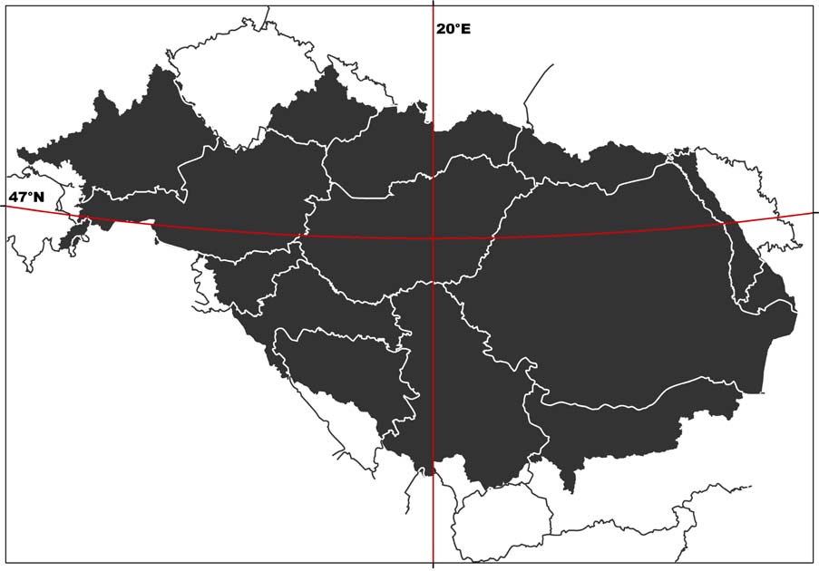
In maps and webmaps available in the DRB GIS, the data will be presented the following way
(compare Figure 7):
> Projection: Lambert Equal-Area Azimuthal
> Central Meridian: 20░
> Reference Latitude: 47░
> Ellipsoid: ETRS89
> Minimum/Maximum scale depends on input data
Figure 7: Data in display projection as stated above
UMWELTBUNDESAMT
DANUBE GIS ş SYSTEM DEFINITION
page 33
4.4. DRB GIS Master Input Data List
The Master Input Data List for the 2nd phase of the DRB GIS ("pragmatic era") consists of the
layers promoted by the WFD GIS Guidance Document13 plus the data already available in the
Danube information system plus the data used for the roof report 2004. Table 1 in Annex A
gives an overview of the datasets (layers) proposed for the DRB GIS. Furthermore, a list of
attributes for each data set has been created wherever possible (see Table 3 in Annex A).
For the 3rd phase ("enhancement era"), the list can be extended with further topics discussed in
the committees.
Since working areas for the DRB are still under discussion, a dataset "working areas" is not
listed at the moment. It is not yet completely clear what that dataset will look like and which
kind of links have to be established to other data sets. It is foreseen, however, to include the
respective field in the templates created for the DRB GIS (compare chapter 5.3.5 "Templates for
data upload").
4.5. Data constraints
It has already been pointed out that it can not be expected that all datasets required will be
available for the DRB GIS immediately and in the accuracy desired. Thus the possible data
constraints have to be listed, the most important being
> lack of data (problem solving has to occur on national level and/or central level,
depending on kind of data)
> harmonisation problems (problem solving: bilaterally)
> generalisation problems (problem solving: centrally within GIS ESG)
> coding problems (problem solving: central level and/or consultant)
The resolution of the input data sets requested for the DRB GIS plays a significant role in
dealing with the tasks listed above.
4.6. CCM vs. EGM14
As the question of using EGM or CCM data for reporting with the DRB GIS was discussed at the
15th RBM EG Meeting in Brussels (October 2004), the Umweltbundesamt was asked to include
an evaluation of the usability of the two datasets for the DRB GIS in this report.
13 Common Implementation Strategy for the Water Framework Directive (2000/60/EC). Guidance Document
No 9 Implementing the Geographical Information System Elements (GIS) of the Water Framework Directive.
Produced by Working Group 3.1 ş GIS.
14 first draft by Kßroly Futaki, Info Mgmt and Admin Officer, ICPDR Secretariat; substantial amendments by
Umweltbundesamt
Reference: JŘrgen Vogt et al.: CCM River and Catchment Database, version 1.0. EUR 20756 EN, June 2003,
compare http://agrienv.jrc.it/activities/pdfs/CCM-Report-EUR20756EN.pdf (31. 1. 2005)
UNDP/GEF DANUBE REGIONAL PROJECT
CHAPTER 4. TASK 3: MASTER INPUT DATA LIST
page 34
4.6.1. Background
Information
CCM Data
In response to an increasing need for more detailed European river network and catchments
data layers for analyses ( i.e. quantity, quality, trend of water resources, environmental
pressures and impacts), the JRC Institute for Environment and Sustainability developed a
European-wide database of drainage networks and catchments boundaries. The resulting data
layers should become part of the Eurostat ş GISCO database.
For the creation of the CCM database, highly automated data processing tools were applied. The
automated extraction of topographic parameters, including valleys and drainage networks, from
digital elevation models (DEMs) is assumed to be a viable alternative to traditional surveys and
manual evaluation of topographic maps. With the algorithms for DEM analyses developed for
CCM, a mapping scale of 1 : 500,000 to 1 : 250,000, should be achieved.
The DEM data used is of 100 or 250 metres grid size; for areas where DEMs at this resolution
could not be acquired (e.g. Iceland, Russia), data from the HYDRO1K global digital elevation
dataset with a 1,000 m grid-cell resolution was used (compare Figure 8).
Figure 8: Grid-cell resolution of the DEM Data as basis for CCM
The area covered with the current version 1.1 of the CCM database extends from the
Mediterranean to northern Scandinavia and from the Atlantic Ocean to roughly 38 degrees
Eastern longitude. Figure 9 shows the CCM river network layer in the Danube River Basin.
UMWELTBUNDESAMT
DANUBE GIS ş SYSTEM DEFINITION
page 35
Figure 9: CCM River Network Layer in the DRB
In line with the recommendations given in the WFD GIS Guidance Document15, the Pfafstetter
coding system has partly been implemented in the CCM database. Pfafstetter codes can be used
directly to determine if discharge in a sub-catchment impacts on a potentially downstream
channel. In principle, this can be achieved without applying specific GIS analysis. However,
Pfafstetter codes are not able to cater completely for lakes and marine waters and further
consideration is required in order to produce a system that adequately covers all waters in an
integrated way.
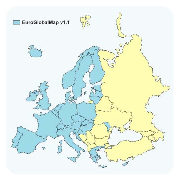
EuroGlobalMap (EGM) Data
EGM16 is a pan-European dataset containing basic geographic information at the scale
1 : 1,000,000. The dataset is harmonised and seamless which means that there are no
gaps/overlappings between graphical objects initially derived from different sources. EGM is
produced in cooperation with the National Mapping and Cadastral Agencies (NMCAs), that is, by
using official national databases. The current release v1.1 of EGM covers 35 European countries
(compare Figure 10).
15 Common Implementation Strategy for the Water Framework Directive (2000/60/EC). Guidance Document
No 9 Implementing the Geographical Information System Elements (GIS) of the Water Framework
Directive. Produced by Working Group 3.1 ş GIS.
16 compare http://www.eurogeographics.org/eng/04_products_globalmap.asp (31. 1. 2005)
UNDP/GEF DANUBE REGIONAL PROJECT
CHAPTER 4. TASK 3: MASTER INPUT DATA LIST
page 36
Figure 10: Coverage of EGM data v1.1
EuroGlobalMap contains the six themes (each including one or several layers):
> Administrative boundary
> Hydrography
> Transport
> Settlements
> Elevation (elevation points)
> Named location (geographical names)
Figure 11 shows the EGM water layer available for the Danube River Basin.
Figure 11: EGM water layer in the DRB
UMWELTBUNDESAMT
DANUBE GIS ş SYSTEM DEFINITION
page 37
4.6.2. Exemplary comparison of EGM, CCM and/or national data
For the evaluation of completeness, topological correctness and the positional accuracy of the
CCM River Network Database, data from Germany, Austria, Hungary and the Czech Republic
were compared to EGM and/or National Data. As for the EGM data, the water line theme of the
EGM's Hydrography layer was used, which contains larger rivers that are presentable at a scale
of 1 : 1 Million. Most of the rivers contained in that dataset are named and selection according
to the river basin size is possible.
Germany
The "Bundesamt fŘr Karthographie und Geodńsie" (Germany)17 compared the CCM data with
the official national river dataset for Germany (DLM100018 and DTK2519) in an investigation
report in 2003. In this study, some severe errors concerning the topological correctness of
rivers were found: in CCM rivers connect that do not meet in the DLM1000, and the order of
confluences along a river in CCM does not correspond to the order in DLM1000 (compare Figure
12). The most eminent discrepancies were found in the flat regions of the country, i.e. in
northern Germany and the Rhine and Danube river plains.
Figure 12: Germany: topological relationship between rivers (DLM1000, CCM)
17 Bundesamt fŘr Kartographie und Geodńsie: Investigation Report: Comparison CCM data with DLM1000
and DTK25. Author Sonja Werhahn, BKG, 24. 7. 2003.
18 Digitales Landschaftsmodell (digital landscape model) 1 : 1,000,000
19 Digitale Topographische Karte (digital topographical map) 1 : 25,000
UNDP/GEF DANUBE REGIONAL PROJECT
CHAPTER 4. TASK 3: MASTER INPUT DATA LIST
page 38
Figure 13 (CCM and EGM data in the same river sections as shown in Figure 12) also
demonstrates the shortcomings of the CCM data. While EGM data match with the national river
data quite well, the topological and positional inaccuracies of the CCM data are evident.
Figure 13: CCM and EGM data for the German Danube
Austria
For an exemplary evaluation of Austrian data, the national river dataset of rivers with
catchments > 100 km▓ (scale comparable to EGM data) was compared to CCM and EGM data.
Data problems occur mainly in the following fields:
> Completeness: rivers in the CCM often are not fully mapped up to their source
(compare Figure 14)
> Topological relationship between rivers: in CCM, rivers connect that do not meet
in the EGM or in the national dataset; the order of the confluences along a river in
CCM does not correspond to the sequence in the compared datasets (compare Figure
15)
> Positional accuracy: the position of the rivers in CCM does not correspond to the
position of the national river system and the EGM (compare Figure 16)
> Harmonisation with other datasets: e.g. administrative borders do not match with
border rivers (compare Figure 17)
While most differences between the datasets observed occur in the flatter Austrian regions
(east), the positional conformance of the CCM improves in the mountainous areas. In direct
comparison with the national river dataset, the EGM water layer shows a high level of
topological correctness and positional accuracy. As becomes most obvious in the example of the
border river March, harmonisation with administrative borders is completely missing and thus
UMWELTBUNDESAMT

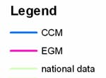
DANUBE GIS ş SYSTEM DEFINITION
page 39
the CCM river data cannot be used for GIS analyses or for (large-scale) cartographic
representation together with other themes.
Figure 14: Incompleteness of CCM in comparison to EGM and national Austrian river
data
Figure 15: CCM/EGM/Austrian national data: topological discrepancies
UNDP/GEF DANUBE REGIONAL PROJECT
CHAPTER 4. TASK 3: MASTER INPUT DATA LIST
page 40
Figure 16: CCM/EGM/Austrian national data: positional discrepancies
Figure 17: CCM/EGM/Austrian national data: Lack of harmonization
UMWELTBUNDESAMT
DANUBE GIS ş SYSTEM DEFINITION
page 41
Hungary
For Hungary examples of the inaccuracies of the CCM dataset in comparison with national river
data were provided. In the Hungarian Plain, the positional inaccuracies stemming from the
method of data creation in the CCM are most obvious; also, the lack of harmonization of river
and lake data is apparent (compare Figures 18 and 19).
Seg1716
Rivseg_HU
Hv-Si-D-ki (1)
Hv-Me-D-ki (2)
HV-Me-D-k÷ (3)
Dv-Me-D-ki (4)
Dv-Me-D-k÷ (5)
Dv-Me-D-na (6)
Dv-Me-D-nn (7)
Dv-Me K-ki (8)
Dv-Me-K-k÷ (9)
Dv-Me-K-na (10)
Sv-Me-D-ki (11)
Sv-Me-D-k÷ (12)
Sv-Me-D-na (13)
Sv-Me-D-nn (14)
Sv-Me-K-ki (15)
Sv-Me-K-ki-ke (16)
Sv-Me-K-k÷ (18)
Sv-Me-K-k÷-ke (17)
Sv-Me-K-na (19)
Sv-Me-K-nn (20)
Sv-Sz-ki (21)
Sv-Sz-ki (22)
Duna, G÷nyű felett (23)
Duna, G÷nyű Ús Baja k÷z÷tt (24)
Duna, Baja alatt (25)
mestersÚges vÝztest (26)
egyÚb vÝzfolyßs (27)
egyÚb csatorna (28)
2
0
2
4
6
8
10 Kilometers
Figure 18: Positional errors in a Section of the river Danube (red dotted line: CCM,
other: Hungarian national data)
Seg1716
Rivseg_HU
Hv-Si-D-ki (1)
Hv-Me-D-ki (2)
HV-Me-D-k÷ (3)
Dv-Me-D-ki (4)
Dv-Me-D-k÷ (5)
Dv-Me-D-na (6)
Dv-Me-D-nn (7)
Dv-Me K-ki (8)
Dv-Me-K-k÷ (9)
Dv-Me-K-na (10)
Sv-Me-D-ki (11)
Sv-Me-D-k÷ (12)
Sv-Me-D-na (13)
Sv-Me-D-nn (14)
Sv-Me-K-ki (15)
Sv-Me-K-ki-ke (16)
Sv-Me-K-k÷ (18)
Sv-Me-K-k÷-ke (17)
Sv-Me-K-na (19)
Sv-Me-K-nn (20)
Sv-Sz-ki (21)
Sv-Sz-ki (22)
Duna, G÷nyű felett (23)
Duna, G÷nyű Ús Baja k÷z÷tt (24)
Duna, Baja alatt (25)
mestersÚges vÝztest (26)
egyÚb vÝzfolyßs (27)
egyÚb csatorna (28)
2
0
2
4
6
8
10 Kilometers
Figure 19: Positional errors in a Section of the river Tisza (red dotted line: CCM, other:
Hungarian national data)
UNDP/GEF DANUBE REGIONAL PROJECT
CHAPTER 4. TASK 3: MASTER INPUT DATA LIST
page 42
Czech Republic
An example from the Czech Republic was taken to show that the CCM dataset, in contrary to the
EGM data, does not contain artificial waterways (compare Figure 20, where the Opatovick Canal
is not contained in CCM data. Also, positional differences in the two river datasets are evident.)
Figure 20: The River Labe and the Opatovick Canal in the Czech Republic
4.6.3. Conclusion
Taking the conclusions drawn from the examination of random checks of CCM data in
comparison with EGM and/or national data as well as other known factors into account, the
usability of the CCM dataset for the DRB GIS has to be assessed as "not good". The CCM
dataset in its current version 1.0 primarily shows the following limitations:
> Especially in flatter regions (e.g. Hungarian Plain), some rivers are not correctly
reported and exhibit distinct positional errors. The positional accuracy of the CCM
database does not seem to correspond to the given map scale of 1 : 250,000 to
500,000, but rather to a much smaller scale.
> The CCM data does not resolve small headwater creeks which results in lack of data
in river's source regions.
> Topological errors (e.g. connecting rivers, wrong sequence of confluences) are
common.
> No artificial waterways are included in the CCM dataset.
> No names for rivers and lakes are contained, which makes searching and selecting
difficult. For cartographic display, names are indispensable.
> The CCM data are not harmonized with other themes, e.g. lakes or administrative
data. Map presentation or GIS analysis together with other layers is not possible in an
error-free manner.
UMWELTBUNDESAMT
DANUBE GIS ş SYSTEM DEFINITION
page 43
> The rivers in CCM can not be selected by their basin size, which is opposed to the
WFD reporting requirements (where rivers are classified according to their catchment
size)
In the light of the experience and errors reported by testing users, it is foreseen to prepare a
second version of the CCM database by July 2005. Besides the correction of obvious errors, the
following issues will be considered in version 2.0:
> application of underlying grid-resolution of 100 x 100 metres
> further study of coding problem and full implementation of a coding system
> naming larger rivers and lakes (catchment size not defined)
> calculation of a set of catchment characteristics and proxy pressure indicators
> recalculation of sub-basins along lake perimeters
> merging of small coastal drainage areas and small drainage areas along lake
perimeters into larger entities
With these improvements in version 2.0, a considerable part of the problems with the CCM
database may be solved. It has to be expected, however, that the following shortcomings of the
CCM data will yet remain prevalent in the new version:
> still does not contain artificial waterways
> still no names for all rivers and lakes
> considerable efforts needed to rectify the problems shown for the water bodies in the
Hungarian Plain or the Danube Delta
> considerable efforts needed to incorporate other themes, like for example the
administrative borders (absolutely not considered within CCM) or lake data
> still no classification of rivers by their basin size possible
Taking into account the above remaining problems, and the commitment of the UNDP/GEF
Danube Regional Project to support ICPDR in this matter, it is advisable for the next two or
three years to continue with the EGM (ver1.1 or higher) until CCM reaches an acceptable level
for the DRB GIS purpose. Not only does EGM represent a more accurate dataset, but its usage
is indispensable ş at least for the first stages of a DRB GIS ş for data harmonization
reasons (compare 4.1.2 "Geometry Framework"). The EGM does not only feature a dataset of
administrative boundaries that stem from the respective NMCAs (and thus are reliable, are
harmonized geometrically between the countries and are updated regularly), but also provides
river data that can function as a framework for transnational data harmonization in the
DRB GIS (river crossing points at boundaries). The use of EGM data is also recommended by the
RBM/GIS ESG in the Summary Report on EGM evaluation20.
After that period (2-3 years) and when CCM data is available in a revised version, the CCM
should be re-analysed for its usability and may well prove a viable solution for DRB-level
reporting then. For countries where no EGM is currently available, the best river dataset
disposable should be used for reporting, the CCM data being one option for that purpose.
20 Summary of the EuroGlobalMap ver. 1.1 National Evaluation Reports, Draft 3 (26 Jan. 2005) by Eva
Sovjßkova (chairperson RBM/GIS ESG), see www.icpdr.org/DANUBIS
UNDP/GEF DANUBE REGIONAL PROJECT
CHAPTER 5. TASK 4: SYSTEM FUNCTIONS
page 44
5. TASK 4: SYSTEM FUNCTIONS
In this chapter, the system functionalities required for creating the geo-information
products defined in Task 2 (Geo-information products) are described. The DRB GIS will be a
web based geo-information system as opposed to a desktop workstation with GIS software.
It is important to note that this web application can not replace any national GIS system - it
would not make (economic) sense to re-build any national GIS on the server of a DRB GIS. The
purpose of the web-based DRB GIS is to combine the datasets of the Danube river basin area in
order to generate a common view on the actual state of the Danube river basin in the
participating countries. Therefore, the web GIS application does not include the whole
functionality of professional GIS software but provides a flexible web mapping and querying
tool for experts as well as for the general public. By making use of the download tool of the
DRB GIS web portal, the users can conduct further specific analyses offline.
The definition of data handling functions and conversion requirements during import or output
processes in the DRB GIS will be described applying an UML method which is commonly used
for describing workflows. These diagrams are called "activity diagrams" and show which part
of the system has to be "activated" to pass results to other components so as to gain an
appropriate result at the end.
Usually, maps produced with GIS software follow specific principles of cartographic design.
These map documents are created for one defined scale and paper format. The purpose of web
mapping is completely different in so far as geodatasets are shown in various scales and
different map extents. The DRB GIS will therefore include printing options and the possibility
to save graphics, but the maps can not ş per definition ş have the same cartographic quality
as cartographically perfected paper maps (for example, labels of features may overlap or
disappear if the zoom level is not appropriate).
The use of system functions that are available as predefined software components is
preferred to programming them at one's own - it is simply much more economical to use
existing solutions than to develop them oneself. Especially in a system that allows user
interaction via a graphical user interface, the error checking phase of the programming
process can be extremely time- and thus cost-consuming. With predefined software
components, almost no error checking is necessary. This decision is also important for the
further maintenance of the system: while a regular update can be expected for predefined
software components, the enhancement of self-made components may consume a considerable
amount of time and money. System functions that are not available as predefined software
components will, however, be developed specially for the DRB GIS framework.
In the following chapter, the specific OGC (Open Geospatial Consortium) and ESRI software
components required for implementing interoperable solutions via the Internet are described.
Furthermore, potential technical problems and limitations of these components in the context of
the Water Framework Directive are pointed out. The descriptions of these solutions can be used
by the ICPDR's representatives and expert groups (RBM, GIS ESG) to come to a decision which
system best meets the requirements of a Danube river basin GIS.
The software architecture is defined with state-of-the-art components as of the end of the year
2004. Should an intermission of several months occur between the system definition and the
implementation of the DRB GIS, the hard- and software requirements should be revised to take
the latest developments into account. Software providers' changes in licensing policies may
result in costs slightly differing from those calculated here.
UMWELTBUNDESAMT
DANUBE GIS ş SYSTEM DEFINITION
page 45
5.1. System configuration & Hardware requirements
The system configuration and hardware requirements depend on which software architecture
will be chosen for the DRB GIS. Basically, there are two main ways to create the DRB geospatial
infrastructure:
> commercial off the-shelf (COTS) GIS software
> open source GIS software
The so-called COTS (commercial off-the-shelf) products are developed by the software
industry to fulfil general tasks in one or more business segments with similar requirements. In
the field of geographic information systems, ESRI is the world leading software provider. The
product portfolio ranges from desktop GIS applications, functional extensions and geo-enabled
databases to geo-viewers and mapping servers. The most important aspects to be taken into
account when using ESRI products are:
> They are commonly used worldwide in the field of professional GIS (ESRI currently
has an approximate 36 percent share of the GIS software market worldwide).
> The ESRI shapefile data format is a widely spread industry standard. Data
exchange with most other GIS software is possible (e.g. Intergraph Geomedia
Professional, Golden Software Surfer etc.).
> When using COTS, the software development costs are reduced, because solutions
are already available (reduces programmatic, technical, schedule, and cost risk).
> Many solutions are already available, but ESRI software is not special-purpose
COTS or COTS used only in specific markets. For the European WFD, no specialised
products are available.
> For long-term systems, maintenance is available and new releases are published
periodically (within the last two years, ESRI has released three updates of its product
line).
> ESRI is member of the Open Geospatial Consortium (OGC) and as such is striving
to provide OGC-compliant software.
On the other hand, there are open source products which have gained a high level of
proficiency over the last few years. The main aspects to consider with open source products are:
> The source code is available. Any changes to the current project are (theoretically)
possible. However, the resources required for the adaptation of code (time and
money) have to be checked in advance.
> If many specific tools have to be developed for a project, open source software is
easier to customize because each function is accessible.
> For specific purposes, tools are already available, while commercial products
(COTS) probably do not consider this business segment as interesting enough to
develop expert software.
> The community of open source software users is more interested in the exchange of
knowledge. Far more user groups, newsgroups and possible solutions for specific
situations are available.
> The advantage of gaining more independence from software industry is in
opposition to potentially higher risks. The further development of open source
software is not always definitely clear.
> Professional support is sometimes difficult to find, and new releases are not
published regularly but only when and if the people involved have enough resources to
UNDP/GEF DANUBE REGIONAL PROJECT
CHAPTER 5. TASK 4: SYSTEM FUNCTIONS
page 46
continue development. The analysts and programmers of the community involved
decide how and at what pace the development goes on.
> Open source software is not freeware. Similar costs as for commercially distributed
software may arise. Further details to open source software are available at
http://www.opensource.org/docs/definition.php (31. 1. 2005)
The DRB GIS is a web-based system that features a long-term planning horizon. While COTS
software like ESRI will be - from the current point of view - enhanced continuously in the
ongoing years, no similar guarantee can be given for open source products.
This report describes three alternatives for the implementation of a DRB GIS. While the first
one concentrates on COTS products, the second portrays an open source alternative. The third
represents a mixture of both, combining the advantages of the first with the advantages of the
second type.
The following figure of the system configuration shows an overview of the main system
functions required by DRB GIS:
Figure 21: System configuration for the DRB GIS (overview)
The system configuration is divided in three tiers:
> Data tier
> Application tier
> Presentation tier
The hardware requirements of the DRB GIS result from the demands for data tier and
application tier - these two system components represent the infrastructure required. The
hardware for a DRB GIS will thus consist of two servers:
> Data server (data tier)
> Application server (application tier)
Both servers should use the same operating system, where we suggest Microsoft Windows
2003 Server.
UMWELTBUNDESAMT
DANUBE GIS ş SYSTEM DEFINITION
page 47
The data server represents the main data pool for the DRB GIS. All datasets that are available
for visualization, querying and download are stored here. Since these datasets need regular
backup, specific access restrictions and because of performance requirements, data tier and
application tier should be separated on two servers.
The application server manages the tools provided by server-side processing. The client
interacts with these software components, but the main program intelligence is situated on the
server. To be able to provide interaction with the data available for the Danube river basin, the
user needs tools for retrieving information, which are provided by the presentation tier of the
system.
The presentation tier consists of the various user interfaces which are implemented server-
based and accessed via the web browser. All the user needs is a web browser; no further
installation is required.
The three alternatives for a DRB GIS as described in the following mainly differ in the usage of
web mapping server software and database software. For the other components, one best-
practice version is described.
5.1.1. Solution 1: COTS products
As already mentioned above, the world leading GIS software producer is ESRI (Environmental
System Research Institute Inc.). Due to the fact that most governments in European countries
are using these products, the COTS solution proposed here is based on ESRI
ArcIMS (Internet Mapping Software).
The following technology portfolio table details the system components required for
Solution 1.
Table 6: Technology portfolio used for COTS solution
System component
Software
Software provider/creation
Operating System
Windows 2003 Server
Microsoft
Database System
ORACLE 10g
ORACLE
Web Mapping Server
ESRI ArcIMS
ESRI
customization of ESRI ArcIMS
Web Mapping Client
DRB GIS solution
webclient
Webserver
Apache HTTP Server Jakarta Tomcat Apache Software Foundation
Jboss jBPM (Java Business
Workflow management DRB GIS solution
Process Management)
Data upload/Data
customization of ESRI ArcIMS
DRB GIS solution
download tool
webclient
Schema mapping
DRB GIS Solution
Validation
DRB GIS Solution
Tomcat & ORACLE 10g
System administration
DRB GIS Solution
database (customization of
tools
built-in functionality)
Geodata management
Fileserver with ESRI Shapefiles
ESRI
Web portal
Java Server Pages
Sun Microsystems
ESRI Image Service, ESRI Feature
ESRI Interfaces
ESRI ArcIMS Server
Service
customization of ESRI ArcIMS
Query Client
DRB GIS Solution
WebClient
UNDP/GEF DANUBE REGIONAL PROJECT
CHAPTER 5. TASK 4: SYSTEM FUNCTIONS
page 48
5.1.2. Solution 2: Open Source products21
The open source solution differs from the COTS solution mainly in the use of different web
mapping software. Depending on the decision if Open Geospatial Consortium (OGC)22 interfaces
should be implemented, two mapping servers are available which could be used. While
GeoServer is OGC's reference implementation and thus a good solution for Web Feature
Services, Deegree is the Web Mapping Server more appropriate for the Web Mapping Service
plus it also implements the Web Feature Service.
Table 7: Technology portfolio used for Open Source solution
System component
Software
Software provider/creation
Operating System
Windows 2003 Server
Microsoft
Database System
MySQL 4.1.7
MySQL AB
Web Mapping Server
(OGC WFS Reference
GeoServer
The GeoServer Project
Implementation)
Web Mapping Server
(OGC WMS Reference
Deegree Webmapping Server
Deegree
Implementation)
customization of webmapping
Web Mapping Client
DRB GIS solution
webclient
Webserver
Apache HTTP Server Jakarta Tomcat Apache Software Foundation
Jboss jBPM (Java Business
Workflow management
DRB GIS solution
Process Management)
Data upload/Data
customization of webmapping
DRB GIS solution
download tool
webclient
Schema mapping
DRB GIS Solution
Validation
DRB GIS Solution
System administration
DRB GIS Solution
Tomcat & ORACLE 10g
tools
database (customization of
built-in functionality)
Geodata management
Fileserver with ESRI Shapefiles
ESRI
Web portal
Java Server Pages
Sun Microsystems
Web Mapping Service (WMS), Web
OGC Interfaces
Feature Service (WFS)
customization of webmapping
Query Client
DRB GIS Solution
webclient
21 for an example for a Web Application implementing OGC services see www.geoland.at (31. 1. 2005)
22 see www.opengeospatial.org (31. 1. 2005)
UMWELTBUNDESAMT
DANUBE GIS ş SYSTEM DEFINITION
page 49
5.1.3. Solution 3: Composite solution (Open Source and COTS products)
Table 8: Technology portfolio used for mixed COTS & Open Source solution
System component
Software
Software provider/creation
Operating System
Windows 2003 Server Microsoft
Database System
MySQL 4.1.7
MySQL AB
Web Mapping Server
ESRI ArcIMS*
ESRI
customization of ESRI ArcIMS
Web Mapping Client
DRB GIS solution
webclient
Apache HTTP Server
Webserver
Apache Software Foundation
Jakarta Tomcat
Jboss jBPM (Java Business
Workflow management
DRB GIS solution
Process Management)
Data upload/Data download
customization of ESRI ArcIMS
DRB GIS solution
tool
webclient
Schema mapping
DRB GIS Solution
Validation
DRB GIS Solution
Tomcat & ORACLE 10g database
DRB GIS Solution
System administration tools
(customization of built-in
functionality)
Fileserver with ESRI
Geodata management
ESRI
Shapefiles
Web portal
Java Server Pages
Sun Microsystems
Web Mapping Service
OGC Interfaces
(WMS), Web Feature
ESRI ArcIMS Server
Service (WFS)
customization of ESRI ArcIMS
Query Client
DRB GIS Solution
WebClient (OGC compliant)
* Linux Red Hat as open source alternative may be used instead, but it has to be clarified if OS
support can be guaranteed. For both systems, know-how and experience are available at the
Umweltbundesamt.
5.1.4. Webmapping server product fact sheets
In 1997, ESRI started in the field of web mapping with ArcView IMS (including a Java based,
pre-packaged web client interface called Map CafÚ). By now, long-term experience has been
incorporated into the software architecture. ESRI ArcIMS has become a high performance,
scalable webmapping software. The workload of interaction with the user occurs mainly on the
server, only the request and the result are sent via the internet.
It is our intention that the DRB GIS should provide access to geo-information products without
installation of any additional software at the client. The only essential installation for every user
is a web browser (e.g. IE 5.5 up, Firefox 1.0 up). As for OGC services, ArcIMS 9.0 presently
only provides the web mapping service (WMS). The previous release, ArcIMS 4.0.1, also
implemented the web feature service (WFS), but the integration of this component in ArcIMS 9
has apparently been postponed to ArcIMS version 9.0.1 or 9.1. The next release is announced
UNDP/GEF DANUBE REGIONAL PROJECT
CHAPTER 5. TASK 4: SYSTEM FUNCTIONS
page 50
for the upcoming year. Instead of OGC compliant WMS and WFS, ArcIMS currently provides its
own standard called ESRI image service and ESRI feature service. Both services are
available for external ArcGIS clients via the internet. Geodata or images of geodata can be
retrieved with desktop software and directly included in geoprocessing tools and models. But
contrary to OGC intentions, these services exclude users of other GIS software products.
Table 9: Product fact sheet - ArcIMS 9.0
ArcIMS 9.0
> memory/RAM: minimum 256 MB RAM recommended per
CPU (all components)
Hardware requirements
> disk space requirements: the disk space requirements for
all ArcIMS components are 602 MB.
> Windows 2000 up
> ArcIMS is only supported on Linux x86, on CPUs that
adhere to the x86 architecture (32-bit), with supported
Linux releases. It is required that the OS (binary) has not
Operating system
been modified. ESRI does not provide any support if
requirements
products are installed on the developer's release of an
operating system. The Linux patches from RHEL AS/ES will
be supported as long as the patches are supported by the
web servers and are from Red Hat without any modification
to the latest kernel/glibc version.
JRE requirements
> JRE version 1.4.2 is supported
Supported Servlet
> Tomcat 4.1.29 with mod_jk2
Engines
> Tomcat 5.0.27 with mod_jk2
> WMS 1.1.1
OGC compliance
> WFS 1.0.0 (only with ArcIMS 4.0.1)
URL
http://www.esri.com/ (31. 1. 2005)
http://www.esri.com/library/whitepapers/pdfs/arcims9-
Documentation
architecture.pdf (31. 1. 2005)
The second web mapping software that is able to support the DRB GIS' use cases is Deegree.
In the year 2000, Deegree (formerly known as Lat/Lon) started as a spin-off of the Institute of
Geography, University of Bonn. The main objective of the Deegree software project is offering
the possibility to build a spatial data infrastructure. Several Open GIS Consortium (OGC) and
ISO/TC 211 standards are implemented. As the whole architecture of Deegree is based on OGC
specifications and concepts, there are no problems to integrate standardized products of other
vendors.
Besides Web Mapping Services (WMS) and Web Feature Service (WFS), further OGC services
like Web Coverage Service (WCS), Web Catalog Service (WCAS), Web Gazetteer Service (WFS-
G), Web Coordinate Transformation Service (WCTS) and Web Terrain Service (WTS) are
available. While WMS and WFS are already widespread and commonly used, some of the other
services still need further conceptual development.
In 2003, the Deegree project was made official reference implementation for the OGC
WMS 1.1.1 specification. Furthermore, the realization of the reference implementations of
UMWELTBUNDESAMT
DANUBE GIS ş SYSTEM DEFINITION
page 51
WCS 1.0.0 and CS-W 2.0 specifications (Catalogue Service-Web) in the context of OWS2
(OpenGIS Web Service Testbed 2) were assigned to Deegree.
Table 10: Product fact sheet - Deegree server
Deegree Webmapping Server
> deegreeWFS 1.2.3 (OGC WFS 1.0.0)
> deegreeWMS 1.1.2 (OGC WMS 1.1.1 reference implementation)
> Memory/RAM: 128 MB RAM for demonstration,
512 MB for optimum application processor (PC)
Hardware requirements
> optimum application hard disk space: 100 MB
(without JDK)
Operating system
> Windows NT up
requirements
> Linux
JRE requirements
> JRE version 1.4.1 up (JDK 1.4.x up)
Supported Servlet Engines
> Tomcat 4.1 up
> deegreeWMS 1.1.2: WMS 1.1.1
OGC compliance
> deegreeWFS 1.2.3: WFS 1.0.0
URL
http://deegree.sourceforge.net/ (31. 1. 2005)
Documentation
http://deegree.sourceforge.net/tec/index.html (31. 1. 2005)
5.1.5. Database product fact sheets
While geometry in the DRB GIS will be stored in shapefiles, the storage of attribute data
requires a database management system. ORACLE Database 10g is an enterprise relational
database management system. The current release is designed for grid computing to gain
more efficiency. Oracle Database 10g provides high quality service which is exceedingly
important for lowering the risk of data loss. The database needs a server with high
performance, enough disc space and also sufficient RAM.
A further reason for choosing ORACLE as software component is that the DANUBIS webportal
currently is based on ORACLE database software, i.e. experience in administrating this kind of
database is available at the ICDPR Secretariat. While the ORACLE application server's
restrictiveness concerning customization has caused some problems for DANUBIS in the past,
the database management system has worked fine so far.
UNDP/GEF DANUBE REGIONAL PROJECT
CHAPTER 5. TASK 4: SYSTEM FUNCTIONS
page 52
Table 11: Product fact sheet - ORACLE
ORACLE 10g Standard edition ONE
> memory/RAM: minimum 512 MB is required
> minimum required swap space is 1 GB. Swap space should
be twice the amount of RAM for systems with 2 GB RAM or
less and between one and two times the amount of RAM
Hardware requirements
for systems with more than 2 GB.
> 2,5 GB of available disk space for the Oracle 10g software
and another 1,2 GB for the database. The /tmp directory
needs at least 400 MB of free space.
> dual processors (e.g. 800 MHz Pentium III CPUs)
> Windows 2000 with service pack 1 or higher, or Windows
Operating system
Server 2003
requirements
> Linux x86 (e.g. Red Hat Enterprise Linux 2.1, Red Hat
Enterprise Linux 3)
Protocol
> TCP/IP
> ODBC
Connectors
> JDBC
> ORACLE SQL*net
MySQL currently is the most popular open source database management system. MySQL
is frequently used for web sites and business systems (e.g. Google) and represents a reliable
alternative to higher-cost, more complex database technology. Its speed, scalability and
reliability have reached a high level of professionalism so as to make it a reasonable choice for
the DRB GIS. MySQL is available under the free software/Open Source GNU general public
license (GPL) or a non-GPL commercial license.
The current generally available release, MySQL 4.1, introduces spatial extensions to allow the
generation, storage, and analysis of geographic features. Although the OpenGIS geometry
model is the basis of these spatial extensions, MySQL diverges from the OpenGIS specification.
The spatial extensions currently are available for MyISAM tables only. Initially, the spatial
extension was considered an alternative to ESRI shapefiles for storing geodata, but two
important arguments oppose this solution:
> Due to the fact that MySQL 4.1 is the first version of MySQL to integrate spatial data,
it does not seem advisable to use it at this early stage.
> The OpenGIS specification for spatial data is not really integrated yet: MySQL only
implements a subset of the OGC's "SQL with Geometry Types environment" proposed
by OGC (this term refers to an SQL environment that has been extended with a set of
geometry types).
As mentioned in the table below, compatibility problems between Linux Red Hat and MySQL
may arise; these have to be adjusted during the prototyping process.
UMWELTBUNDESAMT
DANUBE GIS ş SYSTEM DEFINITION
page 53
Table 12: Product fact sheet - MySQL
MySQL 4.1 Generally Available (GA) release
> dual processor with 512 K cache
Hardware requirements
> a minimum of 200 MBytes is recommended
> 32-bit Windows operating system such as 9x, Me, NT,
2000, XP, or Windows Server 2003
> Windows NT, 2000, XP, 2003 permits to run the MySQL
Operating system
server as a service.
requirements
> MySQL RPMs are currently built on a SuSE Linux 7.3
system, but should work on most versions of Linux that
support rpm and use glibc.
Protocol
> TCP/IP
> ODBC
Connectors
> JDBC via (MySQL Connector/J)
5.2. System functions specification
According to the Needs Assessment23, the core needs for a DRB GIS should be satisfied by a
toolset for information production, handling, and dissemination. The DRB GIS will make
environmental geoinformation available via the Internet and should be the foundation database
for further common (geo)datasets of the Danube River Basin.
The four common needs of user groups identified in the Needs Assessment are:
> maps
> a system on the overview scale
> a centrally initiated and developed GIS database
> public access
The most important system functions of the DRB GIS are outlined in the Strategic Plan24:
> Provide data for Member States GIS
> Receive information from Member States GIS
> Provide information for ICPDR users, Member States GIS, and external users
including the public
The system functions are designed using UML (Unified Markup Language). The use case
diagram is a state-of-the-art way to explain system functions on the basis of a common
language. To facilitate mutual understanding, comments describing the use cases are added. A
detailed specification of the most important use cases is integrated in Annex C. For a detailed
description of special workflows, activity diagrams are added to show when, where, from
whom and how input is required or output should be provided. These diagrams are added to the
tool descriptions when necessary to understand the workflow in the background.
23 Towards a Danube River Basin GIS: Needs Assessment and Conceptual Design for the Danube River Basin
GIS System, KTH, Department of Land and Water Resources Engineering, Stockholm, 2003.
24 Strategic Plan for the development of the DANUBE RIVER BASIN GIS, Zagreb, 16.02.2004
UNDP/GEF DANUBE REGIONAL PROJECT
CHAPTER 5. TASK 4: SYSTEM FUNCTIONS
page 54
Figure 22 delineates the use cases necessary to differentiate. From top to bottom, the roles
within the blue frame (DRB GIS system) successively receive more tools and privileges to
change the input of the system. For example, the data input user may access every tool from
the user above (the expert user), but not from the user below (e.g. the administrator). A
detailed view of the use cases is portrayed in chapters 5.3 (Data handling functions &
conversion requirements), 5.4 (Access & Security functions), and 5.5 (WebGIS client
functionalities and OGC interfaces).
> Public User: any web user who is interested in the condition of the Danube. He/she
will be able to view dynamic maps with a WebGIS application (use case: "views public
WebGIS"). Querying of the database is integrated, but only "pre-defined", simple
queries are available and not the whole content of the DRB GIS database can be
viewed (use case: "calls pre-defined queries").
> Expert user: this user also has access via the Internet but to gain more information
than the public user, special system privileges are provided ("authorized user"). The
expert user inherits all user rights from the public user, and the rights are extended to
viewing more complex maps (use case: "views expert WebGIS") and querying
more information from the database (use case: "creates advanced queries"). This
user has the specialised knowledge to realize when datasets are wrong and can
submit an error message to the data input user (use case: "submits data errors").
Since this user is interested in creating reports (use case: "creates reports") she/he is
usually also has the right (granted by the data input user) to download data (use
case: "downloads data"). The purpose may be creating the WFD roof report (use
case: "creates Roof report") or any other kind of report (use case: "creates any
report").
> Data input user: This user's main activity is the delivery of data to the Danube River
Basin GIS (use case: "uploads data"). The data input user represents the ICPDR
Member States' GIS user who releases the data (and metadata) and who wants to
retrieve GIS data from the DRB GIS (use case: "downloads data", inherited from the
expert user). Before data upload occurs, schema mapping of national data to the
schema of the DRB GIS dataset can be conducted (use case: "maps national data to
DRB schema"). After the decision maker has permitted publication, the data input user
releases the datasets of her/his country to the public WebGIS (use case: "releases
final data version").
> Administrator: The administrator is responsible for maintenance of the whole system
architecture with all its functions. The installation of users and their associated roles is
one of the main tasks of the administrator (use case: "manages users"). She/he is not
involved in the thematic content of the portal but in the appropriateness of the web
application and the database (use case: "administrates portal").
Outside the DRB GIS:
> Reconcile user: This user is a special data input user with extended rights. The
institution/person responsible has to be nominated by neighbouring countries. She/he
supervises the matching of transboundary datasets and thus has to communicate with
national data input users to get commitment to the shared boundary areas (use case:
"reconciles data"). The result of the matching process is submitted to the data input
user. Since the data input user remains responsible for his/her national data and thus
can also reject the reconcile user's suggestion, the reconcile user is an optional role.
UMWELTBUNDESAMT
DANUBE GIS ş SYSTEM DEFINITION
page 55
> There is one decision maker per country who is responsible for the data in a legal
sense. The decision maker permits the publication of data sets (Use case: "permits
publication"). The data input user can release the final data version at her/his
disposition.
Figure 22: Use cases for DRB GIS
While an information system like the DRB GIS provides a toolkit for information supply, business
processes can not be handled solemnly with these tools, but also need support from outside the
actual system. The DRB GIS thus provides a variety of different instruments, while the optimal
workflow also includes aspects that lie beyond the mere technical solution. In Figure 22, the
blue frame comprises the DRB GIS' system scope. The decision maker and the reconcile user,
however, are working in a national legal framework with strong connection to WFD-reporting.
Their main tasks lie outside the actual system, on a higher level of integration (e.g. the role of
the reconcile user includes consultation with the national mapping agencies involved).
UNDP/GEF DANUBE REGIONAL PROJECT
CHAPTER 5. TASK 4: SYSTEM FUNCTIONS
page 56
5.3. Data handling functions & conversion requirements
The geodata format of the DRB GIS is ESRI shapefile which is an industry standard for
exchanging geodatasets. The Water Framework Directive GIS Guidance Document25 recognizes
ESRI shapefile as a possible format for data provision to the European Commission. The
specification of ESRI shapefiles is available at http://www.esri.com/library/whitepapers
/pdfs/shapefile.pdf (31. 1. 2005).
A shapefile stores nontopological geometry and attribute information for the spatial features in a
data set. The geometry for a feature is stored as a shape comprising a set of vector coordinates.
Shapefiles support point, line, and area features. Area features are represented as closed loop,
double-digitized polygons. Attributes are held in a dBASE« format file. Each attribute record
has a one-to-one relationship with the associated shape record. Shapefiles are widely usable,
also in software other than ESRI.
The second geodata format suggested by WFD GIS Guidance Document is GML (Geography
Markup Language). This data format was originally specified and is still further developed by the
Open Geospatial Consortium. ISO/CD 19136 Geographic information - Geography Markup
Language (GML) currently holds the status of "Committee stage", meaning that the standard is
still under discussion. Using standards bears the great advantage that the usage (theoretically)
is not bound to a special software product.
For the time being, the data exchange format chosen for the DRB GIS is shapefile rather than
GML, the main reasons being:
> The GML 3.1 specification is very extensive. For being able to work with it, the
creation of a so-called profile that contains only the required fields would be
necessary.
> ISO 19136 is not published as international standard yet.
> No data available for the Danube river basin are originally GML. Therefore, all data
would have to be exported from their native format, while some data already are
available in shapefile format.
> Due to the fact that not all spatial reference systems are supported, the export of
GML in GIS software often is problematic. Contrary to that, most GIS software
products can import and export shapefiles.
> Shapefiles can contain only one geometry type which helps to keep the datasets
consistent.
> Each web mapping software is able to display shapefiles, while GML may differ
extremely depending on the XML schema used. Profiles fulfilling the demands of the
DRB GIS are not yet available.
25 Common Implementation Strategy for the Water Framework Directive (2000/60/EC). Guidance Document
No 9 Implementing the Geographical Information System Elements (GIS) of the Water Framework
Directive. Produced by Working Group 3.1 ş GIS. p. 60.
UMWELTBUNDESAMT
DANUBE GIS ş SYSTEM DEFINITION
page 57
5.3.1. Nomenclature of DRB GIS data
The following table defines the data-related terms used for the DRB GIS system.
Table 13: Nomenclature of DRB GIS data
Dataset
Description
Single dataset
A single dataset represents the atomic data structure
(table, geodataset) of the system which has been
uploaded into the system from the data input user.
The dataset exists only once in the system, although it
can be reused (referenced) multiple times in product
bundles and categories.
Dataset bundle
Description
Dataset bundle
Dataset bundles group at least two items together. A
bundle comprises more than one dataset and/or dataset
bundle which logically belong together.
Dataset bundle
The term "dataset bundling" does not refer to the
physical storing structure, but allows, for example,
Dataset
bundling datasets which are needed for a specific
reporting obligation.
Dataset bundle
Category
Description
The datasets and/or dataset bundles are grouped into
Category
categories which provide a hierarchical structure for the
portal. A category can contain one ore more
subcategories.
Category
This structuring mechanism can easily be changed in
the future e.g. when more datasets are added, more
Dataset
reporting obligations have to be supported etc.
Categories do not reflect the physical data storing
Dataset bundle
structure, but just allow a structured view at the
datasets.
Each geodataset is stored in geographic coordinate system and no projection is assigned.
5.3.2. Data
download
Only authenticated and authorized users are allowed to download datasets (see chapter 5.4
"Access & Security functions" for details).
Each download dataset consists of a zip file containing:
> table(s) in tab delimited format for data not included in shapefile's dbf-file, e.g. 1:n
joined data of the DRB GIS database
> ESRI shape file(s) containing minimum 3 files for one geodataset with the file
extensions *.shp, *.dbf, and *.shx, plus a projection file (*.prj)
> the corresponding meta data (*.xml).
UNDP/GEF DANUBE REGIONAL PROJECT
CHAPTER 5. TASK 4: SYSTEM FUNCTIONS
page 58
Figure 23: Use case "download data"
Since data ownership is represented by the respective national GIS data input user, only the
data input user can grant data download permissions for one or more of his datasets to other
users. During a process called "security" (check of authentication and authorization), the system
identifies the download user's privileges. If the permission is granted for a category, then all
included categories, dataset bundles and datasets are available to the respective user. In the
case of granting a dataset bundle, all included dataset bundles and datasets are available (see
chapter 5.3.1 "Nomenclature of DRB GIS data"). If the data download user has sufficient rights,
he/she receives a link which enables him to download one or more approved data products. The
whole business process of downloading data is tracked by the workflow management system
that is included in the DRB GIS system (compare chapter 5.3.6 "Workflow management"). This
tool provides an overview via a webpage that summarizes which datasets are available for
download for the respective user.
Activity diagrams detailing the process of downloading data are available in Annex C.
5.3.3. Data
upload
Only authenticated and authorized data input users are allowed to upload datasets, which is
accomplished via a web based data upload tool. Each geodataset is uploaded as a separate zip
file. Tables that are joined to the geodataset in the DRB GIS database have to be included in
this zip file. To guarantee consistency in the system, attribute tables should always be uploaded
together with the geometry files; only in cases where tables cannot be associated to a
geometry, the table can be uploaded on its own.
Each upload dataset consists of a zip file containing:
> Table(s) in tab delimited format for data not included in shapefile's dbf-file, e.g. 1:n
joined data of the DRB GIS database
UMWELTBUNDESAMT
DANUBE GIS ş SYSTEM DEFINITION
page 59
> Maximum one geodataset as ESRI shape file(s) containing minimum 3 files with the
file extensions *.shp, *.dbf, and *.shx, plus a projection file (*.prj). This geodataset is
uploaded together with its joined tables.
> the corresponding meta data (*.xml).
The geodatasets have to be in geographic coordinate system with no projection. The geographic
coordinate systems supported for upload are detailed in Annex D.
The upload process is divided in three separate steps that are executed one after another:
> Physical upload of the data zip file to the DRB GIS webserver
> Data validation
> Storage in the DRB GIS system
Figure 24: Use case "upload data"
After uploading to the server, the datasets are processed according to the rules of the
underlying workflow management system. If the dataset does not conform to the DRB GIS
schema, schema mapping has to be applied. Then the datasets are validated according to the
validation criteria, i.e. the new data are compared to the predefined templates for
completeness, for correct fields data types and for the presence of obligatory field values.
Furthermore, code checking will be implemented for those datasets where codelists are
available. As soon as a dataset of state boundaries has been agreed upon, the incoming data
can also be validated concerning their coherence with the state boundaries (data can only be
uploaded within the boundaries of the data input user's country, compare chapter 4.3 "Data
delivery guidelines").
If the data validation process is completed successfully, data are stored in the DRB GIS system,
and any old versions of the uploaded file moved to the DRB GIS data repository. If the dataset
does not conform to the DRB GIS standards, the file can is not stored in the system. Regardless
of success or failure of the transaction, the outcome of the upload process is submitted to the
data input user in form of a status message. If an error occurred, the user is informed why a
dataset is not appropriate and what he can do to successfully upload the data next time. If no
error occurred, the user is informed of the successful accomplishment of data upload. The
business process of uploading is additionally tracked in the workflow management system.
Overview is provided by a webpage that summarizes which datasets have been successfully
uploaded by which user.
Activity diagrams detailing the process of uploading data are available in Annex C.
UNDP/GEF DANUBE REGIONAL PROJECT
CHAPTER 5. TASK 4: SYSTEM FUNCTIONS
page 60
5.3.4. Schema mapping - integration operations
One major goal of the DRB GIS is to aggregate datasets from different independent sources into
one combined DRB GIS database. For this purpose, schema mapping via a web application
user interface is required. The integration operations are performed with wrappers that
basically function as translators between the remote data schema and the common DRB GIS
data schema. The result is a database conforming to one schema, thus allowing an integrated
view to facilitate attribute querying over the whole Danube river basin.
The wrappers are designed to integrate geodata in the format of ESRI shapefiles. This data
format contains several flat files stored in the file system. The content of the dBase file will be
wrapped and imported to the DRB GIS server. In the process of matching the given datasets to
a common schema, whereupon the wrapper should match only those fields that contain the
same data type (e.g. decimal numbers in local schema to decimal numbers in global schema).
The implementation of a schema mapping tool includes the creation of templates for the
datasets in the master input data list. The templates are used in the prototype phase of the DRB
GIS to check system functions and are then provided to all data input users (see also chapter
5.3.5 "Templates for data upload").
To avoid confusion it has to be pointed out that the term "schema mapping" can denominate the
mapping of table fields as well as the mapping of table values (record mapping or code
translation). Each table consists of records (rows) and fields (columns). The value at the
intersection of one row with one column is the cell value. The mapping process can be
implemented in two ways:
> Mapping fields by data type and field name
e.g. field "Name" of the original dataset is mapped to "Basin_Name" in the common
database of DRB GIS.
> Mapping values by value ranges (code translation)
e.g. cell value in original dataset have different value ranges than WFD reporting
requires
The mapping of fields by data type and field name will be a standard functionality provided in
the DRB GIS. A graphical user interface (GUI) in the DRB GIS portal will allow starting the
mapping process.
The creation of a value ranges mapping tool is not foreseen for the first DRB GIS
implementation, but may be added later if need be. The requirements of a record mapping tool
are:
> providing a user interface with high usability
> programming wrappers for each possible dataset.
> extensive expert knowledge (e.g. knowledge of possible value ranges)
The implementation of a record mapping tool in the first implementation stage of the DRB GIS
would require extensive programming efforts and thus is not recommended for now. In later
project phases, when all possible data sources have been well documented, value range
mapping may prove useful and can be added as an additional tool. For obvious cases (i.e. where
codelists are available), however, the checking of values will be integrated in the validation
process that takes place in the process of data upload (see chapter 5.3.3 "Data Upload" and Use
Cases in Annex C).
UMWELTBUNDESAMT
DANUBE GIS ş SYSTEM DEFINITION
page 61
5.3.5. Templates for data upload
Apart from schema mapping, the DRB GIS will provide shapefile templates, which can be
useful e.g. for institutions who produce the required geodatasets for the first time. These
templates illustrate what the fields in the common schema of the DRB GIS will look like.
Templates for all GIS datasets and DRB GIS database tables will be provided for download.
Further on, schema files (xml schema definition file, *.xsd) will be available for offline
generation of metadata xml files.
Consequently, there are two major ways to upload data to the DRB GIS:
> Download template and use the national GIS system to fill the shapefiles and tables
> Use the schema mapping tool to adjust national data to the DRB GIS database
As has already been pointed out in connection with the master input data list (chapter 4.4), the
creation of so-called working areas for the Danube River Basin is still under discussion. Since
the RBM GIS ESG (10th meeting, September 2004 in Zagreb) expressed its strong approval of
the implementation of working areas for the Danube, an appropriate field will be foreseen in the
templates.
5.3.6. Workflow
management
A workflow defines how the participants in a business process work together to execute a
process from start to finish; the term workflow thus denotes a series of related interactions
between people and a computer system. A tool used for keeping track of the process (i.e.
maintaining the state of process executions) is the workflow management system (WFMS).
Business processes, expressed in activity diagrams, serve as input for the development of a
workflow management tool. Tracking business processes via workflow management gives both
much more control on how the DRB GIS system is working, and on how effectively it is able to
support e.g. data harmonization.
Business processes that are tracked in DRB GIS workflow management system are:
> Data download
> Data upload
> Schema mapping
The workflow management system will be a software component within the DRB GIS. It takes
as input a formal description of business processes according to the system specification and
monitors the state of processes executions. By showing who has done what and when, the
WFMS allows tracking e.g. the data upload or reconciling processes and reproduces the actions
of the persons responsible in a transparent and reliable way. Furthermore, the implementation
of a WFMS allows changing the workflow, like for example integrating additional actors or
processing tasks, in a flexible and cost-effective way.
For the data input user and the expert user the workflow management is visible as a web page
summarizing which data are available, and which processes have already been executed. Each
ready-to-use dataset in this webpage is equipped with a hyperlink that leads the user to the
metadata file provided upon data upload; the XML-file is transformed to a webpage using a style
sheet (eXtensible style sheet, *.xsl).
That way, a quick view on which data are still missing and which are available for the creation of
web maps and for querying the attribute data is possible. Only the system administrator may
change entries to the workflow management if errors of the IT system occur. In any other case,
no manual changes are required.
UNDP/GEF DANUBE REGIONAL PROJECT
CHAPTER 5. TASK 4: SYSTEM FUNCTIONS
page 62
5.4. Access & Security functions
The process of accessing the DRB GIS web application consist of two steps:
> Authentication
> Authorisation
For authentication the user sends her/his username and password. The system allows access
if they are recognised as correct or denies access if any of the two components (username or
password) is not correct.
Depending on which privileges the user is granted by the system administrator, the user may
access the download, upload, query, and webmapping tool. This process is called
authorisation, because specific users are authorized to access specific system functions. In
this chapter, the actors of the DRB GIS are subsumed in roles. Roles own predefined privileges
which are explained in fair detail.
As far as data are concerned, the security mechanism can be set on items (category, dataset
bundle, bundle) which enables the data owner (data input user) to grant/revoke specific
download permission (see chapter 5.3.1 "Nomenclature of DRB GIS data" for further
information).
5.4.1. Public
user
Figure 25: Specific use case(s): public user
The public user is the role of any web user who is interested in the condition of the Danube.
He/she is able to view dynamic maps with a WebGIS application. Usability is most important
because the user may be neither a GIS- nor a database expert nor provide specialised
knowledge about the DRB GIS' content. Querying the database is of course integrated, but only
"pre-defined", simple queries are available and not the whole content of the database can be
viewed. As the user is not authorized to change any content or to query unapproved datasets,
no authentication is necessary. The public user represents the external users especially the
public, but also interested institutions of the Danube river basin.
Table 14: Public user: privileges
Role
Privilege to...
Activity
Viewing of predefined maps on the condition of the
Public user
View public WebGIS
Danube
Receive answers to specific (predefined) questions
Public user
Call predefined queries
concerning the status of the river Danube
UMWELTBUNDESAMT
DANUBE GIS ş SYSTEM DEFINITION
page 63
5.4.2. Expert
user
Figure 26: Specific use case(s): expert user
Every user inherits the rights of the user above (in the use case diagram), so every use case
accessible for the public user is also available for the expert user. As special system roles are
assigned to him (authorized user ş login is required), the expert user's rights are extended to
viewing more complex maps and retrieving more detailed information from the DRB GIS
database. Authentication is therefore obligatory.
The expert user is concerned with creating reports (e.g. the WFD roof report), an activity which
is situated outside of the context of DRB GIS and accomplished by using any kind of text
processing software. The DRB GIS can, however, support the expert user in compiling this
report by allowing the export of web maps as graphics as well as the download of tables. Should
the implementation phase substantiate that reporting is needed as an integral part of the DRB
GIS system, a reporting tool that puts together text, maps, tables and diagrams can be
integrated. For that purpose, further supporting tools would have to be implemented (table
formatting tool, diagram tool etc.).
While the data input user is responsible for the upload of data, the system role of the expert
user is the provision of expert knowledge for the factual control of data. The expert user is able
to recognise data errors which he submits to the data input user who, in turn, has the privileges
to change the DRB GIS data.
Table 15: Expert user: privileges
Role
Privilege to...
Activity (authorization required)
Besides predefined web maps, the option to create
Expert user
View Expert WebGIS
user defined web maps is available
Besides predefined queries, the option to create
Expert user
Create advanced queries
user defined queries is available
Technical data errors are checked during validation
process, factual data errors are checked by the
Expert user
Submit data errors
expert user who submits them to the data input
user
For reporting and other further processing
purposes, tabular data, map graphics or geodata
Expert user
Download data
(data input user has to grant the rights to do so)
may be downloaded
UNDP/GEF DANUBE REGIONAL PROJECT
CHAPTER 5. TASK 4: SYSTEM FUNCTIONS
page 64
5.4.3. Data input user
Figure 27: Specific use case(s): Data input user
This user's main activity is to submit data to the DRB GIS. The data input user represents the
ICPDR Member States' GIS user who delivers the data (and metadata) required for reporting
and who wants to retrieve GIS data from the DRB GIS (e.g. EuroGlobalMap). Validation
mechanisms check whether the uploaded data have any errors and automated feedback is
created.
The user role of the data input user needs the privilege to upload data. If the upload of attribute
data and geometry datasets is successful, they suit the specific requirements of DRB GIS
database. Schema mapping allows the automatic "translation" of field names and attributes
from national GIS systems. The success or failure during the delivery of datasets to the DRB
GIS database will be visible in the workflow management tool which controls the status of the
process. Shapefiles uploaded to DRB GIS system are automatically available in the DRB expert
WebGIS, while publication for public WebGIS needs permission by the decision maker.
The data input user may update/change only datasets of his own country; for other countries'
datasets and maps, only viewing via web map tool and querying via query tool is allowed. As
the role representing the owner of the data he/she has uploaded, it is the data input user who
grants other users the rights for downloading his/her data.
Table 16: Data input user: privileges
Role
Privilege to...
Activity (authorization required)
Data input
Upload of geodatasets, tables and metadata to
Uploads data
user
DRB GIS
Data input
Maps national data to
Schema mapping may be used if national datasets
user
DRB GIS database
differ from DRB GIS schema.
After receiving the permission from the decision
Data input
Releases final data
maker, the final data version is released to the
user
version
public WebGIS
UMWELTBUNDESAMT
DANUBE GIS ş SYSTEM DEFINITION
page 65
5.4.4. System
administrator
Figure 28: Specific use case(s): system administrator
The administrator is responsible for maintenance of the whole system architecture with all its
functions. This user controls the workflow of data input, data change and data commitment by
the data input user. Working products are not committed to the public but remain in the secure
part of the DRB GIS until the data input user releases and the administrator then commits the
final versions to the database. The installation of users and their associated roles is one of the
main tasks of the administrator. She/he is not involved in the thematic content of the portal,
but in the appropriateness of the web application and the database. The administrator is
represented by the GIS manager or one of her/his technical team.
Table 17: System administrator: privileges
Role
Privilege to...
Activity (authorization required)
New users are added only by the system
System
administrator, for each role each country has to
Manages user rights
administrator
nominate one person (where one person can
occupy several roles).
All privileges are granted, but only IT-system
tasks are fulfilled by the system administrator.
System
This role is not involved in the thematic content of
Administrates portal
administrator
the portal (e.g. checking of data errors) but in the
appropriateness of the web application and the
database
UNDP/GEF DANUBE REGIONAL PROJECT
CHAPTER 5. TASK 4: SYSTEM FUNCTIONS
page 66
5.4.5. Decision
maker
Figure 29: Specific use case(s): decision maker
Outside the DRB GIS system's scope, there is one decision maker per country who is
responsible for the data in a legal sense. She/he accepts the results of national GIS data input
and the result of reconciling in the Danube River Basin GIS. She/he decides whether data
should be made available for the public via WebGIS and querying tools.
Table 18: Decision maker: privileges
Role
Privilege to...
Activity (authorization required)
This person grants the data input user permission
Decision
Permits publication
to the release of his country's datasets to the
maker
public WebGIS.
5.4.6. Reconcile
user
Figure 30: Specific use case(s): reconcile user
This user is a special data input user with extended rights. The institution/person responsible
has to be nominated by neighbouring countries for supervising the matching of transboundary
datasets. He/She thus has to communicate with national data input users to get commitment to
the shared boundary areas. The result of the matching process is submitted to the respective
data input user. Since the data input user remains responsible for his/her national data and as
such can also reject the reconcile user's suggestion, the reconcile user is an optional role.
UMWELTBUNDESAMT
DANUBE GIS ş SYSTEM DEFINITION
page 67
Table 19: Reconcile user: privileges
Role
Privilege to...
Activity (authorization required)
This person has read/write access to datasets of
Reconcile
neighbouring countries. After the matching of
Reconcile data
User
boundaries she/he submits the new dataset to the
national data input users.
5.4.7. Summary
of
roles/privileges
Within the system scope, the following privileges are granted:
Table 20: DRB GIS (inside system) - privileges and roles
privileges
I
S
I
S
efined
ing
roles
ebG
ueries
ebG
uerying
ata
ubmit
ata errors
ata
chema
v
iew public
W
pred
q
v
iew Expert
W
a
dvanced
q
Download
d
S
d
Upload
d
S
Mapp
release of
f
inal data
Manage
user
a
dministrate
portal
Public User
x
x
---
---
---
---
---
---
---
---
---
Expert User
x
x
x
x
x
x
---
---
---
---
---
Data Input User
x
x
x
x
x
x
x
x
x
---
---
Administrator
x
x
x
x
x
x
x
x
x
x
x
Further privileges necessary for DRB GIS for users outside the system scope:
Table 21: DRB GIS (outside system) - privileges and roles
privileges
privileges of
permit publication
Reconcile data
roles
Reconcile user
Expert User
---
x
Decision maker
Expert User
x
---
5.5. WebGIS client functionalities & OGC interfaces
The DRB GIS will provide two WebGIS clients (public and expert WebGIS) which are based on
the same technology and are presented in the same look-and-feel. The toolbox of the expert
WebGIS includes more functionality than the public version. In both cases, the WebGIS client's
main task is to serve as viewing tool for geographic data.
UNDP/GEF DANUBE REGIONAL PROJECT
CHAPTER 5. TASK 4: SYSTEM FUNCTIONS
page 68
The graphical user interface includes functions like the following:
Figure 31: WebGIS ş functions
> "Identify" for retrieving database information on geographic objects
> "Zoom in" for enlargement of the current map extent
> "Zoom out" for reduction of the current map extent
> "Zoom to full extent" of Danube river basin
> "Go back" to previous extent
> "Pan" for moving the map extent
> "Search" is the link to the query tool
> "Help" for support
By clicking on the search button, a query mask is provided. The available geodatasets and their
attribute data can be limited to those the user is interested in. Depending on the users'
privileges, only pre-defined queries are available or the user may additionally define his/her
own.
5.5.1. Public
WebGIS
Any analysis produced by experts needs specialised knowledge for correct interpretation. Raw
data is not suitable for public users who lack factual know-how to understand possible errors or
anomalies. Therefore, these users need geoinformation products that minimize the possibility of
misinterpretation while offering a maximum of information from soundly pre-processed data.
Apart from the main purpose of the public WebGIS, the viewing of geodatasets in the form of
maps, retrieving information from the attribute information is required. Basically, there are two
ways to provide the public users with attribute information:
> use the "identify" tool
> use pre-defined queries available in the query tool
The identify tool corresponds to a tool included in every GIS software to get information
connected to one specific geographic object (e.g. to click on the symbol of a city and thus
retrieve e.g. the city name and the number of inhabitants).
Pre-defined queries have to be devised by the system administrator. The result shows
information that the public users can easily understand. By using appropriate symbolization and
classification, differences and similarities are visible at first sight.
5.5.2. Expert
WebGIS
The expert WebGIS looks similar to the public WebGIS but includes more tools to examine the
underlying data. The expert user's focus is not on only viewing geographic information and on
the visual interpretation of values, but rather on the extraction of information as a basis and
illustration e.g. for the creation of reports. The query tool supports the expert user in retrieving
specific data in a chosen spatial extent and allows showing the query results as tabular data or
UMWELTBUNDESAMT
DANUBE GIS ş SYSTEM DEFINITION
page 69
in the map window. The possibility of downloading data allows further processing in an extra-
DRB GIS-environment (e.g. for statistical analysis).
The extension of the public WebGIS towards the expert version results from the
expansion/addition of the following functionalities:
> Expert WebGIS client
> (extended) query tool
> Data download tool
5.5.3. OGC
Interfaces
The Open Geospatial Consortium (OGC) is an international organization that is leading the
development of standards for geospatial and location based services to facilitate interoperability
of GIS data. OGC works with private enterprises and governmental and academic institutions to
create open and extensible software application programming interfaces for GIS and other
mainstream technologies. The specifications are adopted by ISO for the development of
international standards (e.g. Web Mapping Service ISO/DIS 19128).
Two OGC services have to be considered in the system definition phase of the DRB GIS:
> Web Mapping Service (WMS)
http://portal.opengis.org/files/?artifact_id=5316 (31. 1. 2005)
> Web Feature Service (WFS)
https://portal.opengeospatial.org/files/?artifact_id=7176 (31. 1. 2005)
A Web Map Service (WMS) produces an image (e.g. GIF, JPG) of GIS data. The WMS is a
protocol that gives clients access to an image (not the features themselves) of geodata via a
specially structured http request. In that way, the data can be called into an (GIS) application
without being stored on a local hard-disk or network.
If showing georeferenced images is not sufficient, the Web Feature Service provides a useful
possibility. This service is necessary if the client does not only want to view the images of data,
but rather wants to use the actual features (e.g. for analysis and query).
WFS harmonizes the access to data by using a standardized access method:
> Create a new feature instance
> Delete a feature instance
> Update a feature instance
> Get or Query features based on spatial or non-spatial constraints.
Furthermore, the following WFS operations can be carried out:
> GetCapabilities (obligatory)
> GetFeature (obligatory)
> DescribeFeatureType (obligatory)
> Transaction (Insert, Update, Delete) (optional)
> LockFeature (optional)
> GetFeatureWithLock (optional).
Queries are not stated in SQL, but in an OGC XML-based query language called Filter Encoding
Implementation Specification.
One of the main advantages of integrating standard interfaces is that they are developed
independently of a specific software. If the centralized DRB GIS server incorporates, for
example, WMS, the web mapping servers of the participating countries can simply include
UNDP/GEF DANUBE REGIONAL PROJECT
CHAPTER 5. TASK 4: SYSTEM FUNCTIONS
page 70
georeferenced images of these geodatasets in their national webmapping application. In a
further DRB GIS development phase, the centralized DRB GIS server can work the other way
round: the countries provide their data as WMS service, and the central DRB GIS web mapping
server merges these data to one map of the Danube River Basin. If the DRB GIS should be
turned into a decentralized system in the future, both OGC interfaces (WMS and WFS) together
have to be supported (at least) in a forthcoming DRB GIS project phase.
UMWELTBUNDESAMT
DANUBE GIS ş SYSTEM DEFINITION
page 71
6. TASK 5: WORKPLAN AND COSTS
6.1. Workplan
The Workplan shown in Annex E assumes the starting time for DRB GIS implementation to be
June 2005 (which is considered a realistic date when the responsible parties have come to a
decision whether and with whom to implement the DRB GIS and until when
financing/contracting matters can be cleared). In case of any delays the finalization of the
system will be postponed accordingly.
Until October 2005, a first prototype of the system will be developed, featuring a simple
webpage and prototypes of the schema mapping and upload tools that can be tried out with test
datasets.
The further development of the system will take place until August 2006, when the DRB GIS
should ş after a final testing phase ş be finished and ready to go online.
Although the three solutions for the DRB GIS differ in the amounts of time required for their
implementation, one (medium) development time was assumed for the Workplan. Solutions 1
(COTS) and 2 (Open Source) can require marginally less/more development time respectively.
6.2. Estimation of Costs
To provide an overview as well as the details of the costs the implementation and maintenance
of the DRB GIS will generate, Tables 24 and 25 subsume the expected costs while Tables 22
and 23 give details of the person-days and hardware items calculated. Should the system be
implemented and maintained at the Umweltbundesamt, considerable discounts to these costs
can be given: on the one hand, the Umweltbundesamt has the possibility of acquiring hard- and
software components at a reduced price (approx. 30 % off the regular price), and on the other
hand, benefits from synergies with the Umweltbundesamt's IT- infrastructure can be profited
from. The prices given in the tables below are regular hard- and software prices and personnel
costs at a daily rate of 490 respectively. In addition to the annual costs as shown in Table 25,
the replacement of the system's hardware components is due every 3-4 years.
UNDP/GEF DANUBE REGIONAL PROJECT
CHAPTER 6. TASK 5: WORKPLAN AND COSTS
page 72
Table 22: DRB GIS System Implementation ş Workload (person-days)
Solution 2:
Solution 1:
Solution 3:
WP # WP Name
Open
COTS
Composite
Source
1
Database design and development
73
80
80
1.1
Data modelling & Metadata Schema
25
25
25
1.2
Database installation
1
2
2
1.3
Database programming
12
15
15
1.4
Database tests
2
2
2
1.5
Codelist development
8
8
8
1.6
Shapefile templates development
20
20
20
1.7
Security definition (users, roles, privileges)
5
8
8
2
Application development
185
206
185
2.1
Webmapping server installation
1
1
1
2.2
Webmapping server customization
5
8
5
2.3
Webmapping client public
15
20
15
2.4
Webmapping client expert
30
35
30
2.5
Query tool
20
25
20
2.6
Workflow Management & Tool
15
15
15
2.7
Upload Tool
16
20
16
2.8
Download Tool
18
22
18
2.9
Schema Mapping
20
20
20
2.10
Validation
10
10
10
2.11
Web Portal Programming
10
10
10
2.12
OGC-Interface WMS/ESRI Image Service
10
8
10
2.13
OGC-Interface WFS/ESRI Feature Service
15
12
15
3
Project management
35
35
35
3.1
Quality assurance
5
5
5
3.2
Documentation
5
5
5
3.3
Coordination
15
15
15
3.4
Meetings
10
10
10
4
Rollout
32
32
32
4.1
System Testing & Refinement
12
12
12
4.2
User training & Training preparation
5
5
5
4.3
System Architecture Documentation
10
10
10
4.4
Technical Helpdesk for ICPDR
5
5
5
Sum
325
353
332
WP ... work package
the 3 solutions in comparison:
blue:
lowest figures (least person-days required)
red: highest figures (most person-days required)
grey background: same figures in all 3 solutions
UMWELTBUNDESAMT
DANUBE GIS ş SYSTEM DEFINITION
page 73
Table 23: Hardware Specification26
Quantity
Item
Costs ()27
Data Server
7,372
1
ProLiant DL380 G3 Xeon/3,0 (512KB, 1024MB, 1P)
2,351
1
HP 2GB REG PC2-3200 2x1GB DDR Memory
1,025
2
Harddisk 36GB 15K RPM Ultra 320 Hot-Plug
528
2
Harddisk 146GB 10K RPM Ultra 320 Hot-Plug
1,184
2
Redundant Fan (Hot-Plug) for DL380G3
346
2
Hot Plug red Pwr Supply for DL380G4
382
1
Integrated Lights-Out Advanced Pack
323
1
Battery Backed Write Cache Enabler Option Kit
173
1 Assembling
100
1
Service & Support (3 years)
960
Application Server
7,134
1
ProLiant DL380 G3 Xeon/3,0 (512KB, 1024MB, 1P)
2,351
1
HP 2GB REG PC2-3200 2x1GB DDR Memory
1,025
2
Harddisk 72GB 10K RPM Ultra 320 Hot-Plug
634
2
Harddisk 36GB 15K RPM Ultra 320 Hot-Plug
528
2
Redundant Fan (Hot-Plug) for DL380G3
346
2
Hot Plug red Pwr Supply for DL380G4
382
1
Integrated Lights-Out Advanced Pack
323
1
Dual Channel U320 SCSI Host Bus Adapter
312
1
Battery Backed Write Cache Enabler Option Kit
173
1 Assembling
100
1
Service & Support (3 years)
960
Rack
6,161
1
Universal Rack 10642 (42U) Rack Cabinet
1,284
1
Universal Rack Option: Rack 10000 Stabilizer Kit 600mm
168
1
Universal Rack Option: Rack 10642 Side Panel 42U
281
1
Universal Rack Option: Rack 10000 Blanking Panels, 1U (10 pcs.)
45
2
USV R3000 XR
2,966
Rack Power Distribution Unit (PDU) Kit 16A (includes 1x Controller
2
514
Unit and 2x Extension Bars)
1 Monitor
17"
199
1 KVM
switch
560
2 Connecting
cables
90
1
Keyboard + Mouse
54
Backup System
3,300
1 HP
Storage Works 1/8 TAPE Autoloader DLT
2,500
1
Service & Support (3 years)
800
26 all prices as of January 2005, excl. VAT
27 Should the Umweltbundesamt implement the system and acquire the hardware, prices are approximately
4,600 (data server), 4,500 (application server), 5,000 (rack), 3,100 (backup system). (The
Umweltbundesamt has the possibility to acquire hard- and software at a considerably reduced price.)
UNDP/GEF DANUBE REGIONAL PROJECT
CHAPTER 6. TASK 5: WORKPLAN AND COSTS
page 74
Table 24: DRB GIS Cost Estimation ş Implementation 28
Solution 1:
Solution 2:
Solution 3:
Item
COTS ()
Open Source () Composite ()
Personnel29
159,250
172,970
162,680
Hardware30
23,967
23,967
23,967
Data Server
7,372 7,372 7,372
Application Server
7,134 7,134 7,134
Rack31
6,161 6,161 6,161
Backup System32
3,300 3,300 3,300
Software
22,225
8,100
17,800
Operating System for 2 Servers
1,420 1,420 1,420
Oracle 10g Standard Edition One
4,705 n/a
n/a
mySQL 4.1.7
n/a free free
ESRI ArcIMS
10,700 n/a
10,700
Deegree/GeoServer
n/a free n/a
Apache HTTP Server
free free free
Jakarta Tomcat
free free free
Jboss jBPM
free free free
Java Server Pages
free free free
Backup System33
1,400 680
680
Software Installation
4,000 6,000 5,000
Travel Expenses34
5,000
5,000
5,000
Sum (rounded)
210,500
210,000
209,500
Optional: Data Preparation35 (25 person-days)
12,250
28 all prices as of January 2005, excl. VAT
29 according to person-days detailed in Table 22, daily rates 490. Costs are calculated according to
different types of experts involved (expert, senior expert, supervising expert).
30 according to prices detailed in table 23. The lifecycle of the hardware technology is calculated with 4
years; after that period, the hardware should be replaced.
31 Should the system be implemented at the Umweltbundesamt, the DRB GIS hardware can be integrated to
the Umweltbundesamt's infrastructure, which results in less costs for the rack.
32 Should the system be implemented at the Umweltbundesamt, the Umweltbundesamt's backup system can
be used for solutions 1 and 3. For solution 2, the backup hardware listed here has to be acquired in any
case.
33 Should the system be implemented at the Umweltbundesamt, the costs for backup software amount to
280,- ( 140 per server) for all three solutions
34 estimation (5 meetings during system implementation)
35 The preparation of the data already available (i.e. those used for the Roof Report 2004) to meet the DRB
GIS needs is essential for the system's success. As data preparation is however not an integral part of the
development of the system, it is included as an optional matter of expense here. The preparation of Roof
Report 2004-data includes: 1. combination of data to generate datasets as described in Annex A, 2.
conversion to defined reference system & projection, 3. correction of major topological errors, 4.
adaptation of attributes to conform to DRB GIS schema, 5. creation of metadata for each dataset.
Additionally, data mining and the download and adaptation of freely available data that can also be useful
for the DRB GIS is included (e.g. geology, DEM)
UMWELTBUNDESAMT
DANUBE GIS ş SYSTEM DEFINITION
page 75
Table 25: DRB GIS Cost Estimation ş Maintenance (per year)36
Solution 1:
Solution 2:
Solution 3:
Item37
COTS
Open Source
Composite
days38
costs () days
costs () days
costs ()
Software39
3,950
420
2,620
Operating System40
300 300 300
Oracle 10g41
~
1000 n/a
n/a
ESRI ArcIMS40
2,200 n/a 2,200
Backup System
~ 450
~ 120
~ 120
System Administration
78
38,220
98
48,020
82
40,180
Operating System & DBMS42
36 17,640 44 21,560 36 17,640
Application
30 14,700 36 17,640 32 15,680
Backup
12 5,880 18 8,820 14 6,860
Domain43
20
20
20
Sum (rounded)
42,200
48,500
42,800
6.3. BenefitS & Risks
Benefits
The implementation of a DRB GIS provides many advantages for the ICPDR, its expert bodies
and Member States, for decision makers as well as for the general public. Some advantages of
the system have already been pointed out in chapter 2.2 (System Scope and System
Restraints); the most important "general" benefits with regards to WFD implementation and
other reporting obligations are listed in the following.
> The institutionalisation of data harmonization processes and the establishment of
common standards are vital for the creation of high-quality and consistent data in a
common Danube database.
> A common database and thus consistent information increases the awareness about
the status of waters in the DRB and is a prerequisite for good planning and reporting
practice at a basin wide level.
36 all prices as of January 2005, excl. VAT
37 3 year's hardware maintenance by the hardware provider is included in the respective hardware prices
(see table 23); for each further year, additional costs of e.g. ~ 300/sever occur (the servers should,
however, be replaced every 3-4 years)
38 person-days per year (daily rates 490)
39 service contracts with software providers (software assurance); includes upgrades to new versions
(releases)
40 from the second year after purchase onwards (first year's maintenance is covered by software warranty);
should the system be implemented at the Umweltbundesamt, the costs amount to ~ 140,-/year.
41 from the second year after purchase onwards (first year's maintenance is covered by software warranty)
42 Database Management System
43 annual costs for an Internet Domain, e.g. "www.danubegis.org"
UNDP/GEF DANUBE REGIONAL PROJECT
CHAPTER 6. TASK 5: WORKPLAN AND COSTS
page 76
> The creation of a common methodology for bilateral/multilateral data harmonization
does not only facilitate the creation of a common Danube database, but also supports
data sharing and helps to improve communication and sharing expertise between GIS
users in the DRB. Furthermore, executives' and policy-makers' GIS knowledge and
skills are increased and the opportunities and benefits of the technology become
evident.
> As the system caters for different user needs (e.g. GIS experts as well decision makers
unfamiliar with the technology), and the medium "Internet" guarantees easy access to
the data, a better information flow and improvements in the decision-making process
can be obtained.
> The system guarantees continuity for recurrent (reporting) obligations. As all data and
existing products should be linked to or included in the system, duplicate efforts can
be avoided and money saved. While the preparation of the first harmonized database
will require some extra effort from the ICPDR Member States' GIS experts, the system
can facilitate future work.
> Most importantly, the system fulfils the WFD requirement of public information
dissemination. A DRB GIS provides information on the situation of the Danube River
via a tool that can be accessed by a large majority of the population, that is up-to-date
and easily understandable.
Risks
Several factors could jeopardize the successful implementation and maintenance of the DRB GIS
system. By awareness and allowing for mitigating factors, these risks can be minimized.
> The DRB GIS has to cater for several stakeholders who operate on multiple levels
(national and international) and are geographically dispersed. Adequate
communication with all actors involved needs to be taken care of; decision-making
processes can be quite complex and require a fair amount of time. It is thus important
that the timeframe is not calculated to tightly and that communication canals are
defined clearly. The project team installed for the system definition phase (consisting
of a representative of the ICPR, the GEF/DRP, the GIS ESG and the
Umweltbundesamt) proved to be a good forum and should be established in a similar
form for system implementation.
> Since several parties' interests have to be taken into account, the overall complexity of
the DRB GIS system is rather high. The implementation of a basic system that can
later be expanded to cater, for example, for further ICPDR expert group's needs,
appears to be the best approach.
> Financing the system might prove a complex matter; most probably, costs will be
covered from different sources. Although system implementation in several steps is
possible, it should be taken care of that the implementation process is not ripped into
too many parts that complicate the process and lead to duplicate or even multiple
efforts. Even more importantly, the whole system can become obsolete quite quickly
when not maintained properly: adequate system maintenance is one of the crucial
points for a successful DRB GIS and must not be underestimated. The coverage of
system maintenance costs has to be guaranteed.
> Legal obstacles as concerns data harmonization could occur. Solutions have to be
found in coordination with the experts and authorities concerned. Data problems (lack
or minor quality of data) can be a problem for the system's success. The data already
available can function as a basis, but it is the ICPDR Member States' task to further
build up on that basis and enhance the system with better data whenever possible.
UMWELTBUNDESAMT
DANUBE GIS ş SYSTEM DEFINITION
page 77
> Technological risks for the DRB GIS solutions making use of commercial products
(solutions 1 and 3) are low. All products planned are used widely and have proven to
be able to provide the functions required; their ongoing development is guaranteed. As
for the Open Source products (solution 2 mainly), their development cannot be
foreseen. The technological risk is much higher here.
> The risk that the final product does not live up to the user's expectations should be
mitigated with recurrent circles of user input and feedback, as has already been
practiced for the system definition phase.
UNDP/GEF DANUBE REGIONAL PROJECT
DANUBE GIS ş SYSTEM DEFINITION
page 79
CONTACT INFORMATION
Project management:
Ingrid RODER
Spittelauer Lńnde 5
1090 Vienna
Austria
Phone: ++43 (0)1 31304 5357
Fax: ++43 (0)1 31304 3555
Email: ingrid.roder@umweltbundesamt.at
Webpage(s): http://www.umweltbundesamt.at, http://gis.umweltbundesamt.at
Water Framework Directive & GIS experts:
Doris RIEDL
Spittelauer Lńnde 5
1090 Vienna
Austria
Phone: ++43 (0)1 31304 5963
Fax: ++43 (0)1 31304 3555
Email: doris.riedl@umweltbundesamt.at
Webpage(s): http://www.umweltbundesamt.at, http://gis.umweltbundesamt.at
Cordula GÍKE
Spittelauer Lńnde 5
1090 Vienna
Austria
Phone: ++43 (0)1 31304 3580
Fax: ++43 (0)1 31304 3555
Email: cordula.goeke@umweltbundesamt.at
Webpage(s): http://www.umweltbundesamt.at, http://gis.umweltbundesamt.at
UNDP/GEF DANUBE REGIONAL PROJECT
page 80
WebGIS & System architecture experts:
Kerstin PLACER
Spittelauer Lńnde 5
1090 Vienna
Austria
Phone: ++43 (0)1 31304 5318
Fax: ++43 (0)1 31304 3555
Email: kerstin.placer@umweltbundesamt.at
Webpage(s): http://www.umweltbundesamt.at, http://gis.umweltbundesamt.at
Michael HADRBOLEC
Spittelauer Lńnde 5
1090 Vienna
Austria
Phone: ++43 (0)1 31304 5326
Fax: ++43 (0)1 31304 3555
Email: michael.hadrbolec@umweltbundesamt.at
Webpage(s): http://www.umweltbundesamt.at, http://gis.umweltbundesamt.at
UMWELTBUNDESAMT
DANUBE GIS ş SYSTEM DEFINITION ş ANNEXES
page 1
ANNEXES
ANNEX A Master input data list
ANNEX B Metadata
ANNEX C use cases
ANNEX D supported geographic coordinate systems
ANNEX E Workplan
UNDP/GEF DANUBE REGIONAL PROJECT
DANUBE GIS ş SYSTEM DEFINITION ş ANNEXES
page 3
ANNEX A: MASTER INPUT DATA LIST
UNDP/GEF DANUBE REGIONAL PROJECT
DANUBE GIS ş SYSTEM DEFINITION ş ANNEXES
page 5
ANNEX A: MASTER INPUT DATA LIST
Table 1: Geodata list
Description of Geodatalist fieldnames:
geodata_id
unique identifier for geodata set (same geodata_set could be defined in different scales)
geodata_set
name of geodata_set
geodata_description description of geodata set
max_scale
maximum scale denominator for display on a map (this large the data presentation makes sense)
opt_scale
optimal scale denominator for display on a map
min_scale
minimum scale denominator for display on a map (this small the data presentation makes sense)
geodata_type
geodata type shape, raster, ...
geodata_def
geodata definition: shape: polygon, point, line, annotation; raster: raster
table_include
is there a link to a table: y = yes, n = no
Display scale is a data set property that gives information in which range a dataset should be displayable. The individual datasets' scales of origin will be
stored in the Metadata tables. The individual datasets' scales of origin should be in the range from min_scale to max_scale and if available they should be
near the opt_scale. The scale values given are the target that should be reached. Scales in the existing data sets still differ (often considerably) from these
scales. Only for widely available data sets (e.g. CORINE Landcover 250m) the values for scale were taken from the dataset itself.
geodata_set geodata_description
max_scale
opt_scale
min_scale
geodata_type geodata_def
table_include
State State
polygons
100000
250000
1000000
shape polygon
y
AdminBound Administrative
Boundaries
100000
250000
1000000
shape
line
y
AdminEntit Administrative
Entities
100000 250000 1000000 shape
polygon
y
Cities_p Cities
100000 250000 1000000
shape
point
y
Cities_a
Extensive cities (have to be presented as areas)
100000
250000
1000000
shape
polygon
y
UNDP/GEF DANUBE REGIONAL PROJECT
ANNEX A: MASTER INPUT DATA LIST
page 6
geodata_set geodata_description
max_scale
opt_scale
min_scale
geodata_type geodata_def
table_include
Settlement Settlement
Area
100000 250000 1000000 shape
polygon
y
RBD
River basin district Danube
100000
250000
1000000
shape
polygon
y
Rivbasin
Riverbasins and Subbasins (=large catchment
100000 250000 1000000
shape
polygon y
areas)
Catchment
River catchment areas (for all rivers down to a
100000 250000 1000000
shape
polygon y
defined size)
Compauth
Location of competent authorities for WFD in the
100000 250000 1000000
shape
point
y
DRBD
CWbody Coastal
Waters
100000 250000 1000000
shape
polygon y
GWbody Groundwater
Body
100000 250000 1000000
shape
polygon y
RWseg
River Segments - can be combined to
100000 250000 1000000
shape
line
y
RiverWaterBodies
RWseg_a
River Segments - impoundment (the centerline is in 100000 250000 1000000
shape
polygon y
RWseg)
LWseg
Lake Segments - can be combined to
100000 250000 1000000
shape
polygon y
LakeWaterBodies
TWbody TransitionalWaterBody
100000 250000 1000000
shape
polygon y
GWstn
Groundwater Monitoring Station
100000
250000
1000000
shape
point
y
SWstn
Surface Water Monitoring Station
100000
250000
1000000
shape
point
y
Ecoreg
Ecoregions in the DRBD
100000
250000
1000000
shape
polygon
y
PAbird
Bird protection area
100000
250000
1000000
shape
polygon
y
PAdrinkWat
Drinking water protection areas
100000
250000
1000000
shape
polygon
y
PAhabitat
Habitat protection area (FFH)
100000
250000
1000000
shape
polygon
y
PAnutritie Nutritient-sensitive
areas
100000 250000 1000000 shape
polygon
y
PAsignSpec
Economically significant aquatic species protection
100000 250000 1000000
shape
polygon y
areas
UMWELTBUNDESAMT
DANUBE GIS ş SYSTEM DEFINITION ş ANNEXES
page 7
geodata_set geodata_description
max_scale
opt_scale
min_scale
geodata_type geodata_def
table_include
PArecreati Recreational
waters
100000 250000 1000000 shape
polygon
y
Wetland
Major wetlands in the DRBD
100000
250000
1000000
shape
polygon
y
RiskSpot_p
Potential risk spots for accidents
100000
250000
1000000
shape
point
y
RiskSpot_a
Extensive Potential risk spots for accidents(have to
100000 250000 1000000
shape
polygon y
be presented as areas)
ContSite_p Contaminated
sites
100000 250000 1000000 shape
point
y
ContSite_a
Contaminated sites (have to be presented as areas) 100000
250000
1000000
shape
polygon
y
PointSourc
Main point sources of pollution in the DRBD
100000
250000
1000000
shape
point
y
Harbour
Important harbours in the DRBD
100000
250000
1000000
shape
point
y
HydroStruc
Hydraulic structures (e.g. dam, weir, sluice, outlet)
100000
250000
1000000
shape
point
y
Topography
Topographic annotations in the DRBD
100000
250000
1000000
shape
annotation
n
DEM
Digital Elevation Model - SRTM 90
100000
250000
1000000
raster
raster
n
Hillshade
Hillshaded Digital Elevation Model (cartographically
100000 250000 1000000
raster
raster
n
revised)
Geology
Geologic overview of the DRBD
1000000
5000000
10000000
shape
polygon
y
Landuse
Landuse - PELCOM 1 km
250000
1000000
10000000
raster
raster
n
Landuse
Landuse - CORINE 250 m
100000
500000
50000000
raster
raster
n
Precipitat
Overview precipitation of the DRBD
250000
1000000
10000000
raster
raster
n
UNDP/GEF DANUBE REGIONAL PROJECT
ANNEX A: MASTER INPUT DATA LIST
page 8
Table 2: Tables
Description of Tables fieldnames:
table_name
name of the table ş corresponds to geodata set
table_ID
unique identifier for table (max. 10 characters)
table_desc
table description
No classification tables for rasters are included at the moment.
table_ID table_name table_desc
1 Metadata
Metadata
2
State
State description codes and parameters
3
AdminBound Codes for administrative boundaries
4
AdminEntit
Names and codes for administrative entities
5
Cities
City codes and parameters
6 Settlement
Settlement
Area
7
RBD
River basin district
8 Rivbasin
River
basins
9 Catchment
Catchments
10 Compauth
Competent
Authorities
11 CWbody
CoastalWaterBodies
12 GWbody
GroundWaterBodies
13
RWbody
RiverWaterBodies - Link to RWseg
14
River
Rivers - Link to RWseg
15 RWseg River
segments
16
LWbody
LakeWaterBodies - Link to LWseg
17 LWseg Lake
segments
18 TWbody
Transitional
Water
Bodies
19
GWstn
Groundwater Monitoring Stations
20
SWstn
Surface Water Monitoring Stations
21 Ecoreg Ecoregions
22 Protarea
Protected
Areas
23 Wetland
Wetlands
24
RiskSpot
Accident Risk Spots
25 ContSite
Contaminated
Sites
26 PointSourc
Point
Sources
27 Harbour
Harbours
28
HydroStruc Hydrologicals Structures
29 Geology
Geology
UMWELTBUNDESAMT
DANUBE GIS ş SYSTEM DEFINITION ş ANNEXES
page 9
Table 3: Attributes
Important: This is a first draft of the attributes list! The more detailed data modelling will be accomplished during the main design phase.
Description of Attributes fieldnames:
field_id
unique identifier for table field
table_id
link to the table to which the field belongs (key to table_ID in tables table)
attribute_name
name of the attribute
field_name
name of the field (max. 10 char)
field_type
field
type
length
length of the field
attribute_desc
description of the attribute
possible_values
values that can be filled in ş if empty there is a wide range of possible values
keytofield
foreign key to another table (linkedtable)
linkedtable
the table that is linked via foreign key (keytofield)
attribute_name
field_name
field_type
attribute_desc
possible_values
key_to_field linked_table
field_id
table_id
length
1
1
Identificator
ID
number
24
Unique identifier for features in
data set
2
1
MetadataID
META_ID
string
24
Unique code for Metadata
3
1
MetadataPath
META_NAME
string
100 Name of Metadata XML-File
4
2
Identificator
ID
number
24
Unique identifier for features in
data set
5
2
Name
NAME
string
30
name of the state
UNDP/GEF DANUBE REGIONAL PROJECT
ANNEX A: MASTER INPUT DATA LIST
page 10
attribute_name
field_name
field_type
attribute_desc
possible_values
key_to_field linked_table
field_id
table_id
length
6
2
StateNameCode
ISO3166
string
2
state names ISO3166
<<code list>> ISO3166
7
2
PartOfDRBD
DRBD
string
1
shows if state has part of DRBD {Y = part of the DRBD, N =
no part of the DRBD}
8
2
AreaKM2
AREAKM2
number
6,2
official size of the state in sqkm
9 2 Capital
CAPITAL
string 24 Capital City
CTY_CD
Cities
10
2
Government_Seat
GOVERNMENT
string
24
Government Seat
CTY_CD
Cities
11
2
ICPDR_Status
ICPDR
string
20
member status in ICPDR
{FM = full member, AM =
associated member, NM =
no member}
12 2 MetadataID
META_ID
string
24 Link to Metadata
META_ID
Metadata
13
3
Identificator
ID
number
24
Unique identifier for features in
data set
14
3
MetadataID
META_ID
string
24
Unique code for Metadata
15
3
BoundaryType
BND_TYPE
string
6
Code for type of administrative {level0 = state boundaries,
Boundary (e.g. state boundary, level1 = boundaries of first
province boundary, district
level of administrative
boundary)
entities in a state, level2 =
boundaries of second level
of administrative entities,
level3 = boundaries of third
level of administrative
entities, .)
16
4
Identificator
ID
number
24
Unique identifier for features in
data set
17
4
Name
NAME
string
100 Locally used name for
administrative entity
UMWELTBUNDESAMT
DANUBE GIS ş SYSTEM DEFINITION ş ANNEXES
page 11
attribute_name
field_name
field_type
attribute_desc
possible_values
key_to_field linked_table
field_id
table_id
length
18 4 AdminEntityCode
AE_CODE
string
24 Code for administrative entity
19 4 AdminEntityLevel
AE_LEVEL
string
2 Level
of
administrative Entity
{level0 = state, level1 =
first level of administrative
entities in a state, level2 =
second level of
administrative entities,
level3 = third level of
administrative entities, ...)
20
4
MetadataID
META_ID
string
24
Unique code for Metadata
21
5
Identificator
ID
number
24
Unique identifier for features in
data set
22
5
Name
NAME
string
100 name of the city
23 5 CityCode
CTY_CD
string
24 Unique code for city
24
5
Inhabitants
CTY_INHAB
number
8
inhabitants of the city
25 5 MetadataID
META_ID
number 24 Link
to Metadata
META_ID
Metadata
26
7
Identificator
ID
number
24
Unique identifier for features in
data set
27
7
Name
NAME
string
100 Locally used name
28
7
MSCode
MS_CD
string
22
Unique code for a river basin
As per coding guidelines
district within MS
29
7
EuropeanCode
EU_CD
string
24
Unique code for a river basin
As per coding guidelines
district at EU level
30
7
CompetentAuth
AUTH_CD
string
24
Code of the competent
AUTH_CD
Compauth
authority for the RBD
31 7 MetadataID
META_ID
string
24 Link to Metadata
META_ID
Metadata
UNDP/GEF DANUBE REGIONAL PROJECT
ANNEX A: MASTER INPUT DATA LIST
page 12
attribute_name
field_name
field_type
attribute_desc
possible_values
key_to_field linked_table
field_id
table_id
length
32
8
Identificator
ID
number
24
Unique identifier for features in
data set
33
8
Name
NAME
string
100 Locally used name for River
basin
34
8
MSCode
MS_CD
string
22
Unique code for a river basin
As per coding guidelines
within MS
35
8
EuropeanCode
EU_CD
string
24
Unique code for a river basin at As per coding guidelines
EU level
36
8
DistrictCode
DIST_CD
string
24
Code for River Basin District
EU_CD
RBD
the basin belongs to
37
8
AreaKM2
AREAKM2
number
6
Area in square kilometres
38
9
Identificator
ID
number
24
Unique identifier for features in
data set
39
9
CatchmentName
NAME
string
100 Locally used name of a
Catchment
40
9
CatchmentCode
CAT_CD
string
24
Unique code for river
catchment
41
9
RBDCode
RBD_CD
string
24
Code of the RBD the
MS_CD
RBD
Catchment belongs to
42
9
MetadataID
META_ID
string
24
Unique code for Metadata
43
10
Identificator
ID
number
24
Unique identifier for features in
data set
44
10
Name
NAME
string
100 Locally used name
45
10
Address
ADDRESS
string
200 Correspondence Address
46
10
AuthorityCode
AUTH_CD
string
24
Unique code for the competent To be defined
UMWELTBUNDESAMT
DANUBE GIS ş SYSTEM DEFINITION ş ANNEXES
page 13
attribute_name
field_name
field_type
attribute_desc
possible_values
key_to_field linked_table
field_id
table_id
length
authority.
47 10 MetadataID
META_ID
string
24 Link to Metadata
META_ID
Metadata
48
11
Identificator
ID
number
24
Unique identifier for features in
data set
49
11
Name
NAME
string
100 Locally used name
50
11
MSCode
MS_CD
string
22
Unique code for a waterbody
As per coding guidelines
within MS
51
11
EuropeanCode
EU_CD
string
24
Unique code for a waterbody at
EU level
52
11
EcoRegionCode
REGION_CD
string
2
Ecoregion to which a
As per coding guidelines
REGION_CD Ecoreg
waterbody belongs
53
11
System
SYSTEM
string
1
Type of characterization of a
{A, B}
waterbody
54
11
InsertedWhen
INS_WHEN
date
14
Moment of insertion in the
YYYYMMDDhhmmss
database
55
11
InsertedBy
INS_BY
string
15
Acronym of operator
56
11
RiverBasinCode
BASIN_CD
string
24
The code of the parent river
EU_CD
RivBasin
basin (see coding system)
57
11
StatusYear
STATUS_YR
string
4
Year of reporting of waterbody
characterisation
58
11
HeavilyModified
MODIFIED
string
1
Whether the waterbody is
{Y, N}
heavily modified
59
11
Artificial
ARTIFICIAL
string
1
Whether the waterbody is
{Y,N}
artificial
60 11 SalinityTypology
SALINITY
string
1 Salinity
category according to
{F = Freshwater, O =
UNDP/GEF DANUBE REGIONAL PROJECT
ANNEX A: MASTER INPUT DATA LIST
page 14
attribute_name
field_name
field_type
attribute_desc
possible_values
key_to_field linked_table
field_id
table_id
length
Annex II
Oligohaline, M =
Mesohaline, P = Polyhaline,
E = Euhaline}
61
11
DepthTypology
DEPTH_CAT
string
1
Depth category based on mean {S = Shallow <30m, I =
depth
Intermediate 30-200m, D =
Deep >200m}
62
11
Latitude
LAT
number
8,5
Definition not given in WFD.
Can be calculated from
Assume Latitude (in ETRS89) of supplied geometry
mathematical centre of
waterbody
63
11
Longitude
LON
number
8,5
Definition not given in WFD.
Can be calculated from
Assume Longitude (in ETRS89) supplied geometry
of mathematical centre of
waterbody
64
11
TidalTypology
TIDAL
string
5
Not defined ş assume same as {MICRO, MESO,MACRO}
Transitional Tidal range
category according to Annex II
65 11 MetadataID
META_ID
number 24 Link
to Metadata
META_ID
Metadata
66
12
Identificator
ID
number
24
Unique identifier for features in
data set
67
12
Name
NAME
string
100 Locally used name
68
12
MSCode
MS_CD
string
22
Unique code for a waterbody
As per coding guideline
within MS
69
12
EuropeanCode
EU_CD
string
24
Unique code for a waterbody at As per coding guidelines.
EU level
70
12
EcoRegionCode
REGION_CD
string
2
Ecoregion to which a
REGION_CD Ecoreg
UMWELTBUNDESAMT
DANUBE GIS ş SYSTEM DEFINITION ş ANNEXES
page 15
attribute_name
field_name
field_type
attribute_desc
possible_values
key_to_field linked_table
field_id
table_id
length
waterbody belongs
71
12
InsertedWhen
INS_WHEN
date
14
Moment of insertion in the
YYYYMMDDhhmmss
database
72
12
InsertedBy
INS_BY
string
15
Acronym of operator
73
12
RiverBasinCode
BASIN_CD
string
24
The code of the parent river
EU_CD
RivBasin
basin (see coding system)
74
12
Horizon
HORIZON
number
2
Unique identifier for the
horizon, where separate,
overlying bodies exist
75
12
StatusYear
STATUS_YR
string
4
Year of reporting of waterbody
characterisation
76 12 MetadataID
META_ID
string
24 Link to Metadata
META_ID
Metadata
77
13
Identificator
ID
number
24
Unique identifier for features in
data set
78
13
Name
NAME
string
100 Locally used name
As per coding guidelines
79
13
MSCode
MS_CD
string
22
Unique code for a waterbody
within MS
80
13
EuropeanCode
EU_CD
string
24
Unique code for a waterbody at As per coding guidelines
EU level
81
13
EcoRegionCode
REGION_CD
string
2
Ecoregion to which a
REGION_CD Ecoreg
waterbody belongs
82
13
System
SYSTEM
string
1
Type of characterization of a
{A, B}
waterbody
83
13
InsertedWhen
INS_WHEN
date
14
Moment of insertion in the
YYYYMMDDhhmmss
database
UNDP/GEF DANUBE REGIONAL PROJECT
ANNEX A: MASTER INPUT DATA LIST
page 16
attribute_name
field_name
field_type
attribute_desc
possible_values
key_to_field linked_table
field_id
table_id
length
84
13
InsertedBy
INS_BY
string
15
Acronym of operator
85
13
RiverBasinCode
BASIN_CD
string
24
The code of the parent river
EU_CD
RivBasin
basin (see coding system)
86
13
StatusYear
STATUS_YR
string
4
Year of reporting of waterbody
characterisation
87
13
HeavilyModified
MODIFIED
string
1
Whether the waterbody is
{Y, N}
heavily modified
88
13
Artificial
ARTIFICIAL
string
1
Whether the waterbody is
{Y,N}
artificial
89 13 AltitudeTypology
ALT_CAT
string
4
Altitude category according to
{HIGH, MID, LOW}
Annex II
90 13 GeologyTypology
GEOL_CAT
string
1
Geological category according
{C = Calcareous, S=
to Annex II
Siliceous, O = Organic}
91
13
SizeTypology
SIZE_CAT
string
2
Size based on catchment area
{S,M,L,XL}
according to Annex II
92
13
Continua
CONTINUA
string
1
Whether river segment is an
{Y, N}
imaginary link segment to
maintain network topology
93
13
FlowDirection
FLOWDIR
string
1
Flow direction with respect to
{W = With, A = Against}
digitized direction
94
13
Latitude
LAT
number
8,5
Definition not given in WFD.
Can be calculated from
Assume Latitude (in ETRS89) of supplied geometry
mathematical centre of
waterbody
95
13
Longitude
LON
number
8,5
Definition not given in WFD.
Can be calculated from
Assume Longitude (in ETRS89) supplied geometry
UMWELTBUNDESAMT
DANUBE GIS ş SYSTEM DEFINITION ş ANNEXES
page 17
attribute_name
field_name
field_type
attribute_desc
possible_values
key_to_field linked_table
field_id
table_id
length
of mathematical centre of
waterbody
96
13
Geology
GEOLOGY
Not defined
97
13
SizeMeasurement
SIZE
Not defined
98 13 MetadataID
META_ID
string
24 Link to Metadata
META_ID
Metadata
99
14
Identificator
ID
number
24
Unique identifier for features in
data set
100 14
Name
NAME
string
100 river name
101 14
MSCode
RIV_CD
number
24
unique river code
102 14
LengthKM
LENGTHKM
number
6,2
official length of the river
103 14
MetadataID
META_ID
string
24
Link to Metadata
META_ID
Metadata
104 15
Identificator
ID
number
24
Unique identifier for features in
data set
105 15
SegmentCode
SEG_CD
string
24
Unique code for the segment
106 15
RWB_Code
RWB_CD
string
24
Unique code of RiverWater
EU_CD
RWbody
Body to which this segment
belongs
107 15
River_Code
RIV_CD
string
24
Unique code of River to which
RIV_CD
River
segment belongs
108 15
Name
NAME
string
100 Locally used name
109 15
Continua
CONTINUA
string
1
Wheter river segment is an
{Y,N}
imaginary link segment to
maintain network topology
(e.g. imaginary rivers through
lakes)
UNDP/GEF DANUBE REGIONAL PROJECT
ANNEX A: MASTER INPUT DATA LIST
page 18
attribute_name
field_name
field_type
attribute_desc
possible_values
key_to_field linked_table
field_id
table_id
length
110 15
FlowDirection
FLOWDIR
string
1
Flow direction with respect to
{W = With, A = Against}
digitized direction
111 15
WaterwayClass
WATERWAY
string
3
Classification of European
{IV, Va, Vb, VIa, VIb, VIc,
Inland Waterways
VII}
(ECE/TRANS/SC.3/131)
112 15
BoundaryType
BND_TYPE
string
6
Code for type of administrative {level0 = state boundaries, BND_TYPE AdminBound
Boundary (e.g. state boundary, level1 = boundaries of first
province boundary, district
level of administrative
boundary) that is part of the
entities in a state, level2 =
RWseg
boundaries of second level
of administrative entities,
level3 = boundaries of third
level of administrative
entities, ..)
113 15
MetadataID
META_ID
string
24
Link to Metadata
META_ID
Metadata
114 16
Identificator
ID
number
24
Unique identifier for features in
data set
115 16
Name
NAME
string
100 Locally used name
116 16
MSCode
MS_CD
string
22
Unique code for a waterbody
As per coding guidelines
within MS
117 16
EuropeanCode
EU_CD
string
24
Unique code for a waterbody at As per coding guidelines
EU level
118 16
EcoRegionCode
REGION_CD
string
2
Ecoregion to which a
REGION_CD Ecoreg
waterbody belongs
119 16
System
SYSTEM
string
1
Type of characterization of a
{A, B}
waterbody
UMWELTBUNDESAMT
DANUBE GIS ş SYSTEM DEFINITION ş ANNEXES
page 19
attribute_name
field_name
field_type
attribute_desc
possible_values
key_to_field linked_table
field_id
table_id
length
120 16
InsertedWhen
INS_WHEN
date
14
Moment of insertion in the
YYYYMMDDhhmmss
database
121 16
InsertedBy
INS_BY
string
15
Acronym of operator
122 16
RiverBasinCode
BASIN_CD
string
24
The code of the parent river
EU_CD
RivBasin
basin (see coding system)
123 16
StatusYear
STATUS_YR
string
4
Year of reporting of waterbody
characterisation
124 16
HeavilyModified
MODIFIED
string
1
Whether the waterbody is
{Y, N}
heavily modified
125 16
Artificial
ARTIFICIAL
string
1
Whether the waterbody is
{Y,N}
artificial
126 16 AltitudeTypology
ALT_CAT
string
4
Altitude category according to
{HIGH, MID, LOW}
Annex II
127 16 GeologyTypology
GEOL_CAT
string
1
Geological category according
{C = Calcareous, S =
to Annex II
Siliceous, O = Organic)
128 16
SizeTypology
SIZE_CAT
string
2
Size based on catchment area
{S = Small 0.5-1km, M =
according to Annex II
Medium 1-10km, L = Large
10-100km, XL = >100km}
129 16
DepthTypology
DEPTH_CAT
string
1
Depth category based on mean {V = Very Shallow <3m, S
depth
= Shallow 3-15m, D = Deep
>15m}
130 16
Altitude
ALT
Not defined
131 16
Latitude
LAT
number
8,5
Definition not given in WFD.
Can be calculated from
Assume Latitude (in ETRS89) of supplied geometry
mathematical centre of
waterbody
UNDP/GEF DANUBE REGIONAL PROJECT
ANNEX A: MASTER INPUT DATA LIST
page 20
attribute_name
field_name
field_type
attribute_desc
possible_values
key_to_field linked_table
field_id
table_id
length
132 16
Longitude
LON
number
8,5
Definition not given in WFD.
Can be calculated from
Assume Longitude (in ETRS89) supplied geometry
of mathematical centre of
waterbody
133 16
MetadataID
META_ID
string
24
Link to Metadata
META_ID
Metadata
134 17
Identificator
ID
number
24
Unique identifier for features in
data set
135 17
Name
NAME
string
100 Locally used name
136 17
SegmentCode
SEG_CD
string
24
Unique code for the segment
137 17
LWBCode
LWB_CD
string
24
Unique Code of Lake Water
EU_CD
LWBody
Body to which this segment
belongs
138 17
MetadataID
META_ID
string
24
Link to Metadata
META_ID
Metadata
139 18
Identificator
ID
number
24
Unique identifier for features in
data set
140 18
Name
NAME
string
100 Locally used name
141 18
MSCode
MS_CD
string
22
Unique code for a waterbody
As per coding guidelines
within MS
142 18
EuropeanCode
EU_CD
string
24
Unique code for a waterbody at As per coding guidelines
EU level
143 18
EcoRegionCode
REGION_CD
string
2
Ecoregion to which a
REGION_CD Ecoreg
waterbody belongs
144 18
System
SYSTEM
string
1
Type of characterization of a
{A, B}
waterbody
145 18
InsertedWhen
INS_WHEN
date
14
Moment of insertion in the
YYYYMMDDhhmmss
database
UMWELTBUNDESAMT
DANUBE GIS ş SYSTEM DEFINITION ş ANNEXES
page 21
attribute_name
field_name
field_type
attribute_desc
possible_values
key_to_field linked_table
field_id
table_id
length
146 18
InsertedBy
INS_BY
string
15
Acronym of operator
147 18
RiverBasinCode
BASIN_CD
string
24
The code of the parent river
EU_CD
RivBasin
basin (see coding system)
148 18
StatusYear
STATUS_YR
string
4
Year of reporting of waterbody
characterisation
149 18
HeavilyModified
MODIFIED
string
1
Whether the waterbody is
{Y, N}
heavily modified
150 18
Artificial
ARTIFICIAL
string
1
Whether the waterbody is
{Y,N}
artificial
151 18 SalinityTypology
SALINITY
string
1
Salinity category according to
{F = Freshwater, O =
Annex II
Oligohaline, M =
Mesohaline, P = Polyhaline,
E = Euhaline}
152 18
TidalTypology
TIDAL
string
5
Tidal range category according {MICRO, MESO,MACRO}
to Annex II
153 18
Latitude
LAT
number
8,5
Definition not given in WFD.
Can be calculated from
Assume Latitude (in ETRS89) of supplied geometry
mathematical centre of
waterbody
154 18
Longitude
LON
number
8,5
Definition not given in WFD.
Can be calculated from
Assume Longitude (in ETRS89) supplied geometry
of mathematical centre of
waterbody
155 18
MetadataID
META_ID
string
24
Link to Metadata
META_ID
Metadata
156 19
Identificator
ID
number
24
Unique identifier for features in
data set
UNDP/GEF DANUBE REGIONAL PROJECT
ANNEX A: MASTER INPUT DATA LIST
page 22
attribute_name
field_name
field_type
attribute_desc
possible_values
key_to_field linked_table
field_id
table_id
length
157 19
Name
NAME
string
100 Locally used name
158 19
WaterBodyCode
BDY_CD
string
24
Unique code of parent GW
EU_CD
GWbody
Body
159 19
MSCode
MS_CD
string
22
Unique code for a station at MS See coding guidelines.
level
160 19
EuropeanCode
EU_CD
string
24
Unique code for a station at EU See coding guidelines.
level
161 19
InsertedWhen
INS_WHEN
date
14
Moment of insertion in the
YYYYMMDDhhmmss
database
162 19
InsertedBy
INS_BY
string
15
Acronym of operator
163 19
Level
LEVEL
string
1
Station Type
{Y,N}
164 19
Operational
OPERAT
string
1
Station Type
{Y,N}
165 19
Surveillance
SURVEIL
string
1
Station Type
{Y,N}
166 19
Depth
DEPTH
number
4
Depth in metres
167 19
MetadataID
META_ID
number
24
Link to Metadata
META_ID
Metadata
168 20
Identificator
ID
number
24
Unique identifier for features in
data set
169 20
Name
NAME
string
100 Locally used name
170 20
WaterBodyCode
BDY_CD
string
24
Unique code of parent
EU_CD
RWbody,
waterbody
GWbody,
TWbody
171 20
MSCode
MS_CD
string
22
Unique code for a station at MS See coding guidelines.
level
172 20
EuropeanCode
EU_CD
string
24
Unique code for a station at EU See coding guidelines.
level
UMWELTBUNDESAMT
DANUBE GIS ş SYSTEM DEFINITION ş ANNEXES
page 23
attribute_name
field_name
field_type
attribute_desc
possible_values
key_to_field linked_table
field_id
table_id
length
173 20
InsertedWhen
INS_WHEN
date
14
Moment of insertion in the
YYYYMMDDhhmmss
database
174 20
InsertedBy
INS_BY
string
15
Acronym of operator
175 20
Depth
DEPTH
number
4
Depth in metres
176 20
Drinking
DRINKING
string
1
Station Type
{Y,N}
177 20
Investigative
INVEST
string
1
Station Type
{Y,N}
178 20
Operational
OPERAT
string
1
Station Type
{Y,N}
179 20
Habitat
HABITAT
string
1
Station Type
{Y,N}
180 20
Surveillance
SURVEIL
string
1
Station Type
{Y,N}
181 20
Reference
REFERENCE
string
1
Station Type
{Y,N}
182 20
MetadataID
META_ID
string
24
Link to Metadata
META_ID
Metadata
183 21
Identificator
ID
number
24
Unique identifier for features in
data set
184 21
Name
NAME
string
40
Locally used name
185 21
EcoRegionCode
REGION_CD
string
2
Codes as specified by Annex XI {1-25}{AT = Atlantic, NO =
Norwegian, BR = Barents,
NT = North Sea, BA =
Baltic, ME = Mediterranean}
186 21
MetadataID
META_ID
string
24
Link to Metadata
META_ID
Metadata
187 22
Identificator
ID
number
24
Unique identifier for features in
data set
188 22
Name
NAME
string
100 Locally used name
UNDP/GEF DANUBE REGIONAL PROJECT
ANNEX A: MASTER INPUT DATA LIST
page 24
attribute_name
field_name
field_type
attribute_desc
possible_values
key_to_field linked_table
field_id
table_id
length
189 22
ProtectedAreaType
PROT_TYPE
string
1
Category of the protected area {D = Drinking, R =
Recreational, E = Economic
Species, N = Nutrient, H =
Habitat, B = Bird}
190 22
MetadataID
META_ID
string
24
Link to Metadata
META_ID
Metadata
191 6
Identificator
ID
number
24
Unique identifier for features in
data set
192 6
MetadataID
META_ID
string
24
Link to Metadata
193 6
Settlement
SETTLEMENT
string
1
Area is settlement area
{Y,N}
194 23
Identificator
ID
number
24
Unique identifier for features in
data set
195 23
Name
NAME
string
100 Locally used name
196 23
WetlandCode
WET_CD
string
24
Wetland Code
197 23
AreaKM2
AREAKM2
number
6,2
Area in squkm
198 23
MetadataID
META_ID
string
24
Link to Metadata
199 24
Identificator
ID
number
24
Unique identifier for features in
data set
200 24
Name
NAME
string
100 Locally used name
201 24
AcRiskSpotCode
ARS_CD
string
24
Unique code for a Industrial
site that forms a risk spot at
MS level
202 24
AcRiskSpotClass
ARS_CL
number
2
Water risk index
203 24
MetadataID
META_ID
string
24
Link to Metadata
204 25
Identificator
ID
number
24
Unique identifier for features in
data set
UMWELTBUNDESAMT
DANUBE GIS ş SYSTEM DEFINITION ş ANNEXES
page 25
attribute_name
field_name
field_type
attribute_desc
possible_values
key_to_field linked_table
field_id
table_id
length
205 25
Name
NAME
string
100 Locally used name
206 25 ContaminatedSiteCod CS_CD
string
24
Unique code for a
e
contaminated site that forms a
risk spot at MS level
207 25 ContaminatedSiteCla CS_CL
number
2
M1 Methodology
ss
208 26
Identificator
ID
number
24
Unique identifier for features in
data set
209 26
MetadataID
META_ID
string
24
Link to Metadata
210 26
Name
NAME
string
100 Locally used name
211 26
PointSource
PS_CD
string
24
Unique code for point source of
pollution - Link to Parameter
Tables in EMIS
212 26
PointSourceClass
PS_CL
number
2
Kind of Point Source
{A = Agricultural, I =
Industrial, M = Municipal, N
= Nuclear, O = Other}
213 26
SegmentCode
SEG_CD
string
24
Unique code for the river
SEG_CD
RWseg
segment which is recipient of
the discharger (for lakes the
imaginary river through the
lake is the recipient)
214 26
MetadataID
META_ID
string
24
Link to Metadata
215 27
Identificator
ID
number
24
Unique identifier for features in
data set
216 27
Name
NAME
string
100 Locally used name
217 27
HarbourCode
HARBOUR_CD
string
24
Unique code for harbours
UNDP/GEF DANUBE REGIONAL PROJECT
ANNEX A: MASTER INPUT DATA LIST
page 26
attribute_name
field_name
field_type
attribute_desc
possible_values
key_to_field linked_table
field_id
table_id
length
218 27
SegmentCode
SEG_CD
string
24
Unique code for the river
segment where the harbour is
located
219 27
MetadataID
META_ID
string
24
Link to Metadata
220 28
Identificator
ID
number
24
Unique identifier for features in
data set
221 28
Name
NAME
string
100 Locally used name
222 28 HydrologicalStructure HS_CD
string
24
Unique code for the
Code
hydrological structure
223 28
SegmentCode
SEG_CD
string
24
Unique code for the river
segment where the
hydrological structure is located
or where it forms its endpoint
224 28 HydrologicalStructure HS_CL
string
2
Classification of Hydrological
{D = Dam, W = Weir, ...}
Class
Structure
225 28
MetadataID
META_ID
string
24
Link to Metadata
226 29
Identificator
ID
number
24
Unique identifier for features in
data set
227 29
Geology Code
GEOL_CD
string
24
Unique code for geologic types
228 29
MetadataID
META_ID
string
24
Link to Metadata
UMWELTBUNDESAMT
DANUBE GIS ş SYSTEM DEFINITION ş ANNEXES
page 27
ANNEX B: METADATA
UNDP/GEF DANUBE REGIONAL PROJECT
DANUBE GIS ş SYSTEM DEFINITION ş ANNEXES
page 29
ANNEX B: METADATA
Table 1: Metadata
The following Metadata list is based on ISO 19115. To make it easily comparable with the ISO standard, the classes as well as the identification numbers from
the ISO 19115 data dictionary are listed.
Description of Metadata list fieldnames:
Metadata groups
for DRB GIS metadata has been grouped into topics
Metadata Element
metadata element as in ISO 19115
ISO 19115 ID
identification number for object classes entities or class attribute elements as used in ISO 19115 data dictionary
Type
data
type
Cardinality
number of instances the entity or elements may have
Domain value
domain
Obligation
M = mandatory, C = mandatory under certain circumstances (which mostly apply to the Danube GIS ş thus these C -
fields can be seen as mandatory too), O = Optional (some optional elements will be automatically created by the
system
Short name
short name for the entity/element provided by ISO 19115
Short description
description for the entity/element
Data input
is data input necessary ş N = no data input (all rows showing classes have no data input), Y = data input necessary
Examples
one example for the metadata
Comments
comments
UNDP/GEF DANUBE REGIONAL PROJECT
ANNEX B: METADATA
page 30
D
Metadata
Classes/Attributes ISO
ion
ta topics
Element (ISO
Type
Domain
Short description
Examples
Comments
19115
19115)
O 19115 I
Cardinality
Obligat
Short name
Data input
Metada
IS
Metadata
2 MD_Metadata.fileIdentifi Character
1 free text
O mdFileID Unique identifier for
N
file identifier
er
String
the metadata file
Metadata
3 MD_Metadata.language Character
1 ISO 639-2
C mdLang
Metadata language
Y 002
002 = german
language
String
<<CodeList>>
Metadata
4 MD_Metadata.character
Class
1 <<CodeList>> C mdChar
Metadata character
Y 004
004 = utf8 = 8-
character set
Set >>
Character Set
set
bit variable size
MD_CharacterSetCode
Code
UCS Transfer
Format, based on
ISO/IEC 10646
Metadata
6 MD_Metadata.hierarchy
Class
N <<CodeList>> C mdHrLv
Metadata scope
Y 005
005 = dataset
hierarchy
Level >>
Scope Code
level
MD_ScopeCode
Metadata
9 MD_Metadata.dateStam Class
1 Date
mdDateSt Date of metadata
Y 2004-11-
ISO 8601 YYYY-
date stamp
p
creation
16T02:48:21
MM-
DDThh:mm:ss
Metadata
1
MD_Metadata.metadata
Character
1 free text
O mdStanN Metadata standard
Y ISO 19115
standard
0 StandardName
String
ame
name (inkl. profile
name
name)
Metadata
1
MD_Metadata.metadata
Character
1 free text
O mdStanV
Version (profile) of
Y ISO 19115, First
standard
1 StandardVersion
String
er
metadatenstandard
edition, 2003-05-01
version
Metadata
8 MD_Metadata.contact
Class
N CI_Responsible M mdContac responsibe
N
point of
>>
Party
t
person/organisation
Common Metadata
contact
UMWELTBUNDESAMT
DANUBE GIS ş SYSTEM DEFINITION ş ANNEXES
page 31
D
Metadata
Classes/Attributes ISO
ion
ta topics
Element (ISO
Type
Domain
Short description
Examples
Comments
19115
19115)
O 19115 I
Cardinality
Obligat
Short name
Data input
Metada
IS
Responsible
3
CI_ResponsibleParty.ind Character
1 free
text
M rpIndNam Name of responsible Y Roder, Ingrid MMag.
Party
7
ividualName
String
e
person: surname,
5
first name, title
3
CI_ResponsibleParty.org Character
1 free
text
M rpOrgNa
Name of responsible Y Umweltbundesamt
7
anisationName
String
me
organisation
Wien, Abt. GIS
6
3
CI_ResponsibleParty.con Class
1 CI_Contact
O rpCntInfo Adress of responsible N
7
tactInfo >>
organisation
8
3
CI_Contact.phone >>
Class
1 CI_Telephone
O cntPhone Telephone number
N
8
where the person or
8
organisation can be
contacted
4
CI_Telephone.voice Character
N free text
O voiceNum Telephone number
Y 0043-(0)1-31304-
0
String
5900
8
4
CI_Telephone.facsimile Character
N free
text
O faxNum Faxnumber
Y 0043-(0)1-31304-
0
String
3571
9
3
CI_Contact.address >> Class
8
Contact
0
UNDP/GEF DANUBE REGIONAL PROJECT
ANNEX B: METADATA
page 32
D
Metadata
Classes/Attributes ISO
ion
ta topics
Element (ISO
Type
Domain
Short description
Examples
Comments
19115
19115)
O 19115 I
Cardinality
Obligat
Short name
Data input
Metada
IS
3
CI_Adress.deliveryPoint Character
1 free text
O delPoint
Adress (street)
Y Treustra▀e 35
Follows 11180,
8
String
Annex A
1
3
CI_Adress.city Character
1 free text
O city
City
Y Wien
8
String
2
3
CI_Adress.postalCode Character
1 free text
O postCode Postcode
Y 1200
8
String
4
3
CI_Adress.country Character
1 ISO 3166-3
O country
Country
Y AT
Follows ISO 3166
8
String
5
3
CI_Adress.electronicMail Character
N free text
O eMailAdd Email where the
Y ingrid.roder@umwel
8
Address
String
person or
tbundesamt.at
6
organisation can be
contacted
3
CI_ResponsibleParty.rol
Class 1
<<CodeList>>
M role
Function
of
Y 007
007 = party who
7
e
CI_RoleCode
responsible person in
can be contacted
9
the organisation
for acquiring
knowledge about
or acquisition of
the resource
UMWELTBUNDESAMT
DANUBE GIS ş SYSTEM DEFINITION ş ANNEXES
page 33
D
Metadata
Classes/Attributes ISO
ion
ta topics
Element (ISO
Type
Domain
Short description
Examples
Comments
19115
19115)
O 19115 I
Cardinality
Obligat
Short name
Data input
Metada
IS
3
CI_Contact.OnlineResou Class 1
CI_OnlineResou O cntOnline Online Information
N
9
rce >>
rce
Res
that can be used to
0
contact responsible
person or
organisation
3
CI_OnlineResource.linka URL 1
URL
M
linkage
URL
(Uniform Y http://www.umwelt
see IETF
9
ge >>
Resource Locator)
bundesamt.at
RFC1738, IETF
7
RFC 2056
3
CI_Contact.hoursOfServ Character
1 free text
O cntHours Contact hours
Y Mo - Th 09:00 -
9
ice
String
12:00 MEZ
1
3
CI_Contact.contactInstr
Character
1 free
text
O cntInstr Additional
Y Monday: focus vecor
9
uctions
String
information for
data; Thursday:
2
contact
focus raster data
Citation
2
MD_Identification.citatio Class
1 CI_Citation
M idCitation Citation for data
N
4 n >>
resource
Dataset title 3
CI_Citation.title
Character
1 free text
M resTitle
Name for the cited
Y Austrian lake data
6
String
data resource
set 1 : 50.000
a
tion
0
3
CI_Citation.alternateTitl Character
1 free text
O resAltTitle Short name or
Y AT lakes 50
6
e
String
foreign language
1
name for cited
Data Identific
resource
UNDP/GEF DANUBE REGIONAL PROJECT
ANNEX B: METADATA
page 34
D
Metadata
Classes/Attributes ISO
ion
ta topics
Element (ISO
Type
Domain
Short description
Examples
Comments
19115
19115)
O 19115 I
Cardinality
Obligat
Short name
Data input
Metada
IS
Dataset
3
CI_Citation.date >>
Class
N CI_Date
M resRefDat Refencedate for cited N
reference
6
e
resource
date
2
3
CI_Date.date
Class
1 Date
M refDate
Referencedate
Y 2004-11-
ISO 8601 YYYY-
9
16T02:48:21
MM-
4
DDThh:mm:ss
3
CI_Date.dateType
Class
1 <<CodeList>> M refDateTy Event used for
Y 001
001 = creation
9
CI_DateTypeCo
pe
reference date
5
de
Dataset
3
CI_Citation.edition
Character
1 free text
O resEd
Version of cited
Y Version 03
edition
6
String
resource
3
3
CI_Citation.editionDate Class
1 Date
M resEdDat
Version date
Y 2004-11-
6
e
16T03:18:44
4
Keywords
5
MD_Keywords.keyword Character
N free text
M keyword
Keywords or Phrases Y Lakes
AThesaurus
2
String
that describe the
should be
data set
created
Dataset topic 4
MD_DataIdentification.t
Class
N <<Enumeratio
C tpCat
Main theme of the
Y 012
012 = Inland
category
1 opicCategory
n>>MD_TopicC
data set
Waters
ategoryCode
UMWELTBUNDESAMT
DANUBE GIS ş SYSTEM DEFINITION ş ANNEXES
page 35
D
Metadata
Classes/Attributes ISO
ion
ta topics
Element (ISO
Type
Domain
Short description
Examples
Comments
19115
19115)
O 19115 I
Cardinality
Obligat
Short name
Data input
Metada
IS
Abstract
2
MD_DataIdentification.a Character
1 free text
M idAbs
Brief narrative
Y The dataset was
describing
5 bstract
String
summary of the
created in the lake
the dataset
contents of the
project 2002 and
resource
contains lakes
greate than 10000
sqm
2
MD_Identifier.authority Class
1 CI_Responsible O identAuth Person or party
N
0
Party
responsible for
6
maintenance of the
namespace
2
MD_Identifier.code
Character
1 free text
M identCode Alphanumeric value
Y
0
String
identifying an
7
instance in the
namespace
Cited
3
CI_Citation.citedRespon Class
N CI_Responsible O citRespPa Person or party
N
Responsible
6
sibleParty
Party
rty
responsible for the
Party
7
cited resource
Dataset
3
MD_DataIdentification.la Character
N ISO 639-2
M dataLang Language that was
Y 002
002 = german
language
9 nguage
String
<<CodeList>>
used for the resource
Dataset
4
MD_DataIdentification.c Class
N <<CodeList>>
C dataChar Name of character
Y 004
004 = utf8 = 8-
character set 0 haracterSet
MD_CharacterS
coding standard
bit variable size
etCode
UCS Transfer
Format, based on
ISO/IEC 10646
UNDP/GEF DANUBE REGIONAL PROJECT
ANNEX B: METADATA
page 36
D
Metadata
Classes/Attributes ISO
ion
ta topics
Element (ISO
Type
Domain
Short description
Examples
Comments
19115
19115)
O 19115 I
Cardinality
Obligat
Short name
Data input
Metada
IS
Status
2
MD_DataIdentification.s Class
N <<CodeList>> O idStatus
Resource status
Y 001
001 = completed
8 tatus
MD_ProgressCo
de
Spatial
3
MD_DataIdentification.s Class
N <<CodeList>> O spatRpTy Method of spatial
Y 001
001 = vector
Representati
7 patialRepresentationTyp
MD_SpatialRep
pe
representation
on
e
resentation
Type Code
Spatial
3
MD_DataIdentification.s Class
N <<Union>>
M dataScale Factor which provides N
Resolution
8 patialResolution
MD_Resolution
a general
understanding of the
density of spatial
data in the dataset
6
MD_Resolution.distance Class
1 Distance
M scaleDist Ground sample
Y 20
1
distance
Geographic
3
EX_GeographicBounding Class
1 -180 <=
M westBL
Western-most
Y 9
9░
location of
4
Box.westBoundLongitud
Longitude >=
coordinate of the
the dataset
4 e
180
limit of the dataset
(4
extent in decimal
coordinates
degrees
or
geographic
identifier)
UMWELTBUNDESAMT
DANUBE GIS ş SYSTEM DEFINITION ş ANNEXES
page 37
D
Metadata
Classes/Attributes ISO
ion
ta topics
Element (ISO
Type
Domain
Short description
Examples
Comments
19115
19115)
O 19115 I
Cardinality
Obligat
Short name
Data input
Metada
IS
3
EX_GeographicBounding Class
1 -180 <=
M eastBL
Eastern-most
Y 18
18░
4
Box.eastBoundLongitude
Longitude >=
coordinate of the
5
180
limit of the dataset
extent in decimal
degrees
3
EX_GeographicBounding Class
1 -90 <=
M southBL
Southern-most
Y 45
45░
4
Box.southBoundLatitude
Latitude >= 90
coordinate of the
6
limit of the dataset
extent in decimal
degrees
3
EX_GeographicBounding Class
1 -90 <=
M northBL
Northern-most
Y 47
47░
4
Box.northBoundLatitude
Latitude >= 90
coordinate of the
7
limit of the dataset
extent in decimal
degrees
Use
6
MD_Constraints.useLimi Character
N Free text
O useLimit
Limitation affecting
Y For
data
Limitation
8 tation
String
the fitness for use of
presentation in
the resource or
scales between 1 :
metadata.
25.000 and 1 :
Data
Constraints
250.000
UNDP/GEF DANUBE REGIONAL PROJECT
ANNEX B: METADATA
page 38
D
Metadata
Classes/Attributes ISO
ion
ta topics
Element (ISO
Type
Domain
Short description
Examples
Comments
19115
19115)
O 19115 I
Cardinality
Obligat
Short name
Data input
Metada
IS
Constraints 7
MD_LegalConstraints.ac Class N
<<CodeList>>
O accessCo
Access constraints
Y 005
005 = license
0 cessConstraints
MD_Restriction
nsts
applied to assure the
Code
protection of privacy
or intellectual
property, and any
special restrictions or
limitations on
obtaining the
resource or
metadata.
7
MD_LegalConstraints.us Class N
<<CodeList>>
O useConst
Constraints applied to Y 005
005 = license
1 eConstraints
MD_Restriction
s
assure the protection
Code
of privacy or
intellectual property,
and any special
restrictions or
limitations or
warnings on using
the resource or
metadata
7
MD_LegalConstraints.ot
Character
N Free text
C othConsts Other restrictions and Y
2 herConstraints
String
legal prerequisites for
accessing and using
the resource or
metadata
UMWELTBUNDESAMT
DANUBE GIS ş SYSTEM DEFINITION ş ANNEXES
page 39
D
Metadata
Classes/Attributes ISO
ion
ta topics
Element (ISO
Type
Domain
Short description
Examples
Comments
19115
19115)
O 19115 I
Cardinality
Obligat
Short name
Data input
Metada
IS
7
MD_SecurityConstraints. Class 1
<<CodeList>>
M class
Name of Restriction
Y 003
003
=
4 classification
MD_Classificati
for Data or Metadata
confidential, i.e.
onCode
use
for internal use
only
7
MD_SecurityConstraints. Character
1 Free text
O userNote Explanation of the
Y copyright
5 userNote
String
application of the
Umweltdaten GmbH
legal constraints or
other restrictions and
legal prerequisites for
obtaining and using
the resource or
metadata
Reference
1
RS_ReferenceSystem.na Class
1 RS_Identifier
M refSysNa
Reference system
N
System
9
me
me
name
6
2
RS_Identifier.codeSpace Character
1 Free text
O identCode Name or identifier of Y ESRI
0
String
Space
person or
8
organisation who
creates the projection
name
y
stem
e S
2
MD_Identifier.code
Character
1 Free text
M identCode Alphanumeric value
Y MGI_Lambert_Austri
0
String
identifying an
a
7
instance in the
Referenc
namespace
UNDP/GEF DANUBE REGIONAL PROJECT
ANNEX B: METADATA
page 40
D
Metadata
Classes/Attributes ISO
ion
ta topics
Element (ISO
Type
Domain
Short description
Examples
Comments
19115
19115)
O 19115 I
Cardinality
Obligat
Short name
Data input
Metada
IS
2
MD_EllipsoidParameters. Real
1 >0.0
M semiMajA Radius of the
Y 6377397,15500000
0
semiMajorAxis
x
equatorial axis of the
0300000000
2
ellipsoid
2
MD_EllipsoidParameters. Class
1 UomLength
M axisUnits Units of the semi-
Y meters
0
axisUnits
(documented in
major axis
3
ISO 19103)
2
MD_EllipsoidParameters. Real
1 >0.0
M denFlatRa Ratio of the
Y 299,152812799999
0
denominatorOfFlattenin
t
difference between
990000
4 gRatio
the equatorial and
polar radii of the
ellipsoid to the
equatorial radius
Projection
2
MD_ProjectionParameter Integer
1 Integer
O zone
Zone number (e.g. in Y
1
s.zone
UTM)
6
2
MD_ProjectionParameter Real
2 Real
O stanParal Standard parallels
Y 46
1
s.standardParallel
7
2
MD_ProjectionParameter Real
1 Real
O lonCntMe Central meridian
Y 13,3333333333333
1
s.longitudeOfCentralMeri
r
333
8 dian
2
MD_ProjectionParameter Real
1 Real
O latProjOri Central latitude
Y 47,5
1
s.latitudeOfProjectionOri
9 gin
UMWELTBUNDESAMT
DANUBE GIS ş SYSTEM DEFINITION ş ANNEXES
page 41
D
Metadata
Classes/Attributes ISO
ion
ta topics
Element (ISO
Type
Domain
Short description
Examples
Comments
19115
19115)
O 19115 I
Cardinality
Obligat
Short name
Data input
Metada
IS
2
MD_ProjectionParameter Real
1 Real
O falEasting False Easting
Y 400000
2
s.falseEasting
0
2
MD_ProjectionParameter Real
1 Real
O falNorthin False Northing
Y 400000
2
s.falseNorthing
g
1
2
MD_ProjectionParameter Class
1 UomLength
O falENUnit Units of False Easting Y meters
2
s.falseEastingNorthingU
19103
s
and False Northing
2 nits
2
MD_ProjectionParameter Real
1 >0.0
O sclFacEqu Ratio between
Y 1
2
s.scaleFactorAtEquator
physical distance and
3
corresponding map
distance, along the
equator
2
MD_ProjectionParameter Real
1 Real
O sclFacCnt Ratio between
Y
2
s.scaleFactorAtCenterLin
physical distance and
7 e
corresponding map
distance along the
centre line
UNDP/GEF DANUBE REGIONAL PROJECT
ANNEX B: METADATA
page 42
D
Metadata
Classes/Attributes ISO
ion
ta topics
Element (ISO
Type
Domain
Short description
Examples
Comments
19115
19115)
O 19115 I
Cardinality
Obligat
Short name
Data input
Metada
IS
2
MD_ProjectionParameter Real
1 Real
O sclFacPrO Multiplier for
Y
2
s.scaleFactorAtProjectio
r
reducing a distance
9 nOrigin
obtained from a map
by computation or
scaling to the actual
distance at the
projection origin
7
DQ_DataQuality.scope Class
1 DQ_Scope
M DataQual Data quality
N
is instantiated
9
information
DQ_Scope
1
DQ_Scope.level
Class
1 <<CodeList>> M scpLvl
Detailed description
Y 005
005 = dataset
3
MD_ScopeCode
about the level of the
8
data specified by the
Data Quality
scope
UMWELTBUNDESAMT
DANUBE GIS ş SYSTEM DEFINITION ş ANNEXES
page 43
D
Metadata
Classes/Attributes ISO
ion
ta topics
Element (ISO
Type
Domain
Short description
Examples
Comments
19115
19115)
O 19115 I
Cardinality
Obligat
Short name
Data input
Metada
IS
8
LI_lineage.statement
Character 1 Free text
M statemen General explanation
Y The data has been
3
String
t
of the data
extracted from the
producer's knowledge
Austrian Digital
about the lineage of
landscape model 1 :
a dataset
50.000 and was
complemented with
information that was
gathered via a
questionnaire from
the app. 2000
Austrian
administrative
communities.
Topology
1
MD_VectorSpatialRepres Class
1 <<CodeList>>
C topLvl
Code which identifies Y 004
004 = full planar
7
entation.topologylevel
MD_TopologyLe
the degree of
graph (topolgy
7
velCode
complexity of the
that usually
tails
spatial relationships
applies to the 2D
vector space of
Data De
gis-data)
UNDP/GEF DANUBE REGIONAL PROJECT
ANNEX B: METADATA
page 44
D
Metadata
Classes/Attributes ISO
ion
ta topics
Element (ISO
Type
Domain
Short description
Examples
Comments
19115
19115)
O 19115 I
Cardinality
Obligat
Short name
Data input
Metada
IS
Geometric
1
MD_GeometricObjects
Class
1 <<CodeList>>
M geoObjTy Name of point or
Y
Objects
8
MD_Geometric
p
vector objects used
4
ObjectTypeCod
to locate zero-, one-,
e
two-, or three-
dimensional spatial
locations in the
dataset
UMWELTBUNDESAMT
DANUBE GIS ş SYSTEM DEFINITION ş ANNEXES
page 45
Table 2: Metadata Codelists
ISO 639-2 Language Code
ID
Name
Domain-Code
Definition
1
dan
001
Danish
2
ger
002
German
3
eng
003
English
4
est
004
Estonian
5
fin
005
Finnish
6
fre
006
French
7
gre
007
Greek
8
ita
008
Italian
9
lav
009
Latvian
10
lit
010
Lithuanian
11
mlt
011
Maltese
12
dut
012
Dutch, Flemish
13
pol
013
Polish
14
por
014
Portuguese
15
swe
015
Swedish
16
slo
016
Slovak
17
slv
017
Slovenian
18
spa
018
Spanish
19
cze
019
Czech
20
hun
020
Hungarian
21
alb
021
Albanian
22
bos
022
Bosnian
23
bul
023
Bulgarian
24
scr
024
Croatian
25
mac
025
Macedonian
26
mol
026
Moldovian
27
rum
027
Romanian
28
scc
028
Serbian
29
ukr
029
Ukrainian
UNDP/GEF DANUBE REGIONAL PROJECT
ANNEX B: METADATA
page 46
B.5.2 Date type Code
ID
Name
Domain-Code
Definition
1
CI_DateTypeCode
DateTypCd
identification of when a given event occurred
2
creation
001
date identifies when the resource was brought into
existence
3
publication
002
date identifies when the resource was issued
4
revision
003
date identifies when the resource was examined
or re-examined and improved or amended
B.5.5 Role Code
ID
Name
Domain-Code
Definition
1
CI_RoleCode
RoleCd
function performed by the responsible party
2
resourceProvider
001
party that supplies the resource
3
custodian
002
party that accepts accountability and responsibility
for the data and ensures appropriate care and
maintenance of the resource
4
owner
003
party that owns the resource
5
user
004
party who uses the resource
6
distributor
005
party who distributes the resource
7
originator
006
party who created the resource
8
pointOfContact
007
party who can be contacted for acquiring
knowledge about or acquisition of the resource
9
principalInvestigato 008
key party responsible for gathering information
r
and conducting research
10
processor
009
party who has processed the data in a manner
such that the resource has been modified
11
publisher
010
party who published the resource
B.5.10 Character Set Code
ID
Name
Domain-Code
Definition
1
MD_CharacterSetCo CharSetCd
name of the character coding standard used for the
de
resource
2
ucs2
001
16-bit fixed size Universal Character Set, based on
ISO/IEC 10646
3
ucs4
002
32-bit fixed size Universal Character Set, based on
ISO/IEC 10646
4
utf7
003
7-bit variable size UCS Transfer Format, based on
ISO/IEC 10646
5
utf8
004
8-bit variable size UCS Transfer Format, based on
ISO/IEC 10646
UMWELTBUNDESAMT
DANUBE GIS ş SYSTEM DEFINITION ş ANNEXES
page 47
6
utf16
005
16-bit variable size UCS Transfer Format, based on
ISO/IEC 10646
7
8859part1
006
ISO/IEC 8859-1, Information technology ş 8-bit
single-byte coded graphic character sets ş Part 1
Latin alphabet No. 1
8
8859part2
007
ISO/IEC 8859-2, Information technology ş 8-bit
single-byte coded graphic character sets ş Part 2
Latin alphabet No. 2
9
8859part3
008
ISO/IEC 8859-3, Information technology ş 8-bit
single-byte coded graphic character sets ş Part 3
Latin alphabet No. 3
10
8859part4
009
ISO/IEC 8859-4, Information technology ş 8-bit
single-byte coded graphic character sets ş Part 4
Latin alphabet No. 4
11
8859part5
010
ISO/IEC 8859-51, Information technology ş 8-bit
single-byte coded graphic character sets ş Part 5
Latin/Cyrillic alphabet
12
8859part6
011
ISO/IEC 8859-6, Information technology ş 8-bit
single-byte coded graphic character sets ş Part 6
Latin/Arabic alphabet
13
8859part7
012
ISO/IEC 8859-7, Information technology ş 8-bit
single-byte coded graphic character sets ş Part 7
Latin/Greek alphabet
14
8859part8
013
ISO/IEC 8859-8, Information technology ş 8-bit
single-byte coded graphic character sets ş Part 8
Latin/Hebrew alphabet
15
8859part9
014
ISO/IEC8859-9, Information technology ş 8-bit
single-byte coded graphiccharacter sets ş Part 9
Latin alphabet No. 5
16
8859part11
015
thai code set
17
8859part14
016
latin-8 code set
18
8859part15
017
latin-9 code set
19
jis
018
japanese code set used for electronic transmission
20
shiftJIS
019
japanese code set used on MS-DOS based
machines
21
eucJP
020
japanese code set used on UNIX based machines
22
usAscii
021
united states ASCII code set (ISO 646 US)
23
ebcdic
022
ibm mainframe code set
24
eucKR
023
korean code set
25
big5
024
taiwanese code set
26
8859part10
025
latin-6 code set
27
8859part13
026
latin-7 code set
UNDP/GEF DANUBE REGIONAL PROJECT
ANNEX B: METADATA
page 48
B.5.11 Classification Code
ID
Name
Domain-Code
Definition
1
MD_ClassificationCo
de
2
unclassified
001
available for general disclosure
3
restricted
002
not for general disclosure
4
confidential
003
available for someone who can be entrusted with
information
5
secret
004
kept or meant to be kept private, unknown or
hidden from all but a selected group of people
B.5.15 MD_GeometricObjectTypeCode
ID
Name
Domain-Code
Definition
1
MD_GeometricObje
GeoObjTypCd name of point or vector objects used to locate
ctType Code
zero-, one-, two-, or three-dimensional spatial
locations in the dataset
2
complex
001
set of geometric primitives such that their
boundaries can be represented as a union of other
primitives
3
composite
002
connected set of curves, solids or surfaces
4
curve
003
bounded, 1-dimensional geometric primitive,
representing the continuous image of a line
5
point
004
zero-dimensional geometric primitive, representing
a position but not having an extent
6
solid
005
bounded, connected 3-dimensional geometric
primitive, representing the continuous image of a
region of space
7
surface
006
bounded, connected 2-dimensional geometric
primitive, representing the continuous image of a
region of a plane
B.5.23 Progress Code
ID
Name
Domain-Code
Definition
1
MD_ProgressCode ProgCd
status of the dataset or progress of a review
2
completed
001
production of the data has been completed
3
historicalArchive
002
data has been stored in an offline storage facility
4
obsolete
003
data is no longer relevant
5
onGoing
004
data is continually being updated
6
planned
005
fixed date has been established upon or by which
the data will be created or updated
UMWELTBUNDESAMT
DANUBE GIS ş SYSTEM DEFINITION ş ANNEXES
page 49
7
required
006
data needs to be generated or updated
8
underDevelopment 007
data is currently in the process of being created
B.5.24 Restriction Code
ID
Name
Domain-Code
Definition
1
MD_RestrictionCode RestrictCd
limitation(s) placed upon the access or use of the
data
2
copyright
001
exclusive right to the publication, production, or
sale of the rights to a literary, dramatic, musical,
or artistic work, or to the use of a commercial print
or label, granted by law for a specified period of
time to an author, composer, artist, distributor
3
patent
002
government has granted exclusive right to make,
sell, use or license an invention or discovery
4
patentPending
003
produced or sold information awaiting a patent
5
trademark
004
a name, symbol, or other device identifying a
product, officially registered and legally restricted
to the use of the owner or manufacturer
6
license
005
formal permission to do something
7
intellectualProperty
006
rights to financial benefit from and control of
Rights
distribution of non-tangible property that is a result
of creativity
8
restricted
007
withheld from general circulation or disclosure
9
otherRestrictions
008
limitation not listed
B.5.25 Scope Code
ID
Name
Domain-Code
Definition
1
MD_ScopeCode
ScopeCd
class of information to which the referencing
entity applies
2
attribute
001
information applies to the attribute class
3
attributeType
002
information applies to the characteristic of a
feature
4
collectionHardware 003
information applies to the collection hardware
class
5
collectionSession
004
information applies to the collection session
6
dataset
005
information applies to the dataset
7
series
006
information applies to the series
8
nonGeographicData 007
information applies to non-geographic data
set
9
dimensionGroup
008
information applies to a dimension group
10
feature
009
information applies to a feature
UNDP/GEF DANUBE REGIONAL PROJECT
ANNEX B: METADATA
page 50
11
featureType
010
information applies to a feature type
12
propertyType
011
information applies to a property type
13
fieldSession
012
information applies to a field session
14
software
013
information applies to a computer program or
routine
15
service
014
information applies to a capability which a service
provider entity makes available to a service user
entity through a set of interfaces that define a
behaviour, such as a use case
16
model
015
information applies to a copy or imitation of an
existing or hypothetical object
17
nationalContribution 016
information applies to the national contribution to
the dataset
B.5.26 Spatial Representation Type Code
ID
Name
Domain-Code
Definition
1
MD_SpatialReprese
SpatRepTypCd method used to represent geographic information
ntationTypeCode
in the dataset
2
vector
001
vector data is used to represent geographic data
3
grid
002
grid data is used to represent geographic data
4
textTable
003
textual or tabular data is used to represent
geographic data
5
tin
004
triangulated irregular network
6
stereoModel
005
three-dimensional view formed by the intersecting
homologous rays of an overlapping pair of images
7
video
006
scene from a video recording
B.5.27 Topic Category Code
ID
Name
Domain-Code
Definition
1
MD_TopicCategoryC TopicCatCd
high-level geographic data thematic classification
ode
to assist in the grouping and search of available
geographic data sets. Can be used to group
keywords as well. Listed examples are not
exhaustive. NOTE: It is understood there are
overlaps between general categories and the user
is encouraged to select the one most appropriate.
2
farming
001
rearing of animals and/or cultivation of plants
Examples: agriculture, irrigation, aquaculture,
plantations, herding, pests and diseases affecting
crops and livestock
3
biota
002
flora and/or fauna in natural environment
Examples: wildlife, vegetation, biological sciences,
ecology, wilderness, sealife, wetlands, habitat
UMWELTBUNDESAMT
DANUBE GIS ş SYSTEM DEFINITION ş ANNEXES
page 51
4
boundaries
003
legal land descriptions Examples: political and
administrative boundaries
5
climatologyMeteorol 004
processes and phenomena of the atmosphere
ogyAtmosphere
Examples: cloud cover, weather, climate,
atmospheric conditions, climate change,
precipitation
6
economy
005
economic activities, conditions and employment
Examples: production, labour, revenue, commerce,
industry, tourism and ecotourism, forestry,
fisheries, commercial or subsistence hunting,
exploration and exploitation of resources such as
minerals, oil and gas
7
elevation
006
height above or below sea level Examples:
altitude, bathymetry, digital elevation models,
slope, derived products
8
environment
007
environmental resources, protection and
conservation Examples: environmental pollution,
waste storage and treatment,
environmental,impact assessment, monitoring
environmental risk, nature reserves, landscape
9
geoscientificInforma 008
information pertaining to earth sciences
tion
Examples: geophysical features and processes,
geology, minerals, sciences,dealing with the
composition, structure and origin of the earth's
rocks, risks of earthquakes, volcanic activity,
landslides, gravity information, soils, permafrost,
hydrogeology, erosion
10
health
009
health, health services, human ecology, and
safety Examples: disease and illness, factors
affecting health, hygiene, substance abuse, mental
and physical health, health services
11
imageryBaseMapsE
010
base maps Examples: land cover, topographic
arthCover
maps, imagery, unclassified images, annotations
12
intelligenceMilitary
011
military bases, structures, activities Examples:
barracks, training grounds, military transportation,
information collection
13
inlandWaters
012
inland water features, drainage systems and their
characteristics Examples: rivers and glaciers, salt
lakes, water utilization plans, dams, currents,
floods, water quality, hydrographic charts
14
location
013
positional information and services Examples:
addresses, geodetic networks, control points,
postal zones and services, place names
15
oceans
014
features and characteristics of salt water bodies
(excluding inland waters) Examples: tides, tidal
waves, coastal information, reefs
UNDP/GEF DANUBE REGIONAL PROJECT
ANNEX B: METADATA
page 52
16
planningCadastre
015
information used for appropriate actions for future
use of the land Examples: land use maps, zoning
maps, cadastral surveys, land ownership
17
society
016
characteristics of society and cultures Examples:
settlements, anthropology, archaeology, education,
traditional beliefs, manners and customs,
demographic data, recreational areas and
activities, social impact assessments, crime and
justice, census information
18
structure
017
man-made construction Examples: buildings,
museums, churches, factories, housing,
monuments, shops, towers
19
transportation
018
means and aids for conveying persons and/or
goods Examples: roads, airports/airstrips, shipping
routes, tunnels, nautical charts, vehicle or vessel
location, aeronautical charts, railways
20
utilitiesCommunicati 019
energy, water and waste systems and
on
communications infrastructure and services
Examples: hydroelectricity, geothermal, solar and
nuclear sources of energy, water purification and
distribution, sewage collection and disposal,
electricity and gas distribution, data
communication, telecommunication, radio,
communication networks
B.5.28 MD_TopologyLevelCode
ID
Name
Domain-Code
Definition
1
MD_TopologyLevelC TopoLevCd
degree of complexity of the spatial relationships
ode
2
geometryOnly
001
geometry objects without any additional structure
which describes topology
3
topology1D
002
1-dimensional topological complex ş commonly
called "chain-node" topology
4
planarGraph
003
1-dimensional topological complex that is planar.
(A planar graph is a graph that can be drawn in a
plane in such a way that no two edges intersect
except at a vertex.)
5
fullPlanarGraph
004
2-dimensional topological complex that is planar.
(A 2-dimensional topological complex is commonly
called "full topology" in a cartographic 2D
environment.)
6
surfaceGraph
005
1-dimensional topological complex that is
isomorphic to a subset of a surface. (A geometric
complex is isomorphic to a topological complex if
their elements are in a one-to-one, dimensional-
and boundry-preserving correspondence to one
UMWELTBUNDESAMT
DANUBE GIS ş SYSTEM DEFINITION ş ANNEXES
page 53
another.)
7
fullSurfaceGraph
006
2-dimensional topological complex that is
isomorphic to a subset of a surface
8
topology3D
007
3-dimensional topological complex. (A topological
complex is a collection of topological primitives
that are closed under the boundary operations.)
9
fullTopology3D
008
complete coverage of a 3D Euclidean coordinate
space
10
abstract
009
topological complex without any specified
geometric realisation
UNDP/GEF DANUBE REGIONAL PROJECT
DANUBE GIS ş SYSTEM DEFINITION ş ANNEXES
page 55
ANNEX C: USE CASES
UNDP/GEF DANUBE REGIONAL PROJECT
DANUBE GIS ş SYSTEM DEFINITION ş ANNEXES
page 57
ANNEX C: USE CASES
The following form sheets do not include all possible use cases but provide an overview of
the main tasks of Danube River Basin GIS.
1
USE CASE: DATA DOWNLOAD TOOL (UC_1)
ID: UC_1
Use Case Data Download Tool
The authorized download user retrieves the datasets which where granted to
Short description
him by the owner (data input user).
Sub Use Case from ---
Has Sub Use
---
Case(s)
Actor(s)
data input user, download user
Triggered by
Download user
The datasets, databundles or categories are downloaded.
Output
if authorization fails: Information message from whom the download user
may obtain the permission to download data.
When the user is logging in, the system checks his authentification (user
name and password) and authorization (access to data and tools). The data
Precondition(s)
input user has granted the download user download rights for the respective
datasets.
The download user has the datasets on local harddisk or netwrk for further
After fulfillment
processing.
Depending on his permission, the download user may not only download
Comment(s)
data but also templates. These templates represent geodatasets and tables
necessary for the DRB GIS database.
UNDP/GEF DANUBE REGIONAL PROJECT
ANNEX C: USE CASES
page 58
ACTIVITY DIAGRAM: USAGE OF DOWNLOAD TOOL (AC_11)
Activity Diagram to Use Case Data Download (UC_1)
ID: AC_11
Usage of download tool
The information message informs the download user that he does not
have sufficient user rights to download the data required. It states
Comment(s)
who is responsible for these datasets so that he/she can contact the
data input user who may grant the relevant rights.
UMWELTBUNDESAMT
DANUBE GIS ş SYSTEM DEFINITION ş ANNEXES
page 59
ACTIVITY DIAGRAM: GRANTING OF PRIVILEGES (AC_12)
Activity Diagram to Use Case Data Download (UC_1)
ID: AC_12
Granting of privileges
The data input user is allowed to grant privileges to the download
user but only for the datasets he owns. If a category is selected, all
included datasets and data bundles are granted.
Comment(s)
If there are legal restrictions that prohibit the transmission of the
required data, the data input user has to obtain permission from the
decision maker.
UNDP/GEF DANUBE REGIONAL PROJECT
ANNEX C: USE CASES
page 60
USE CASE: DATA UPLOAD (UC_2)
ID: UC_2
Upload of data to DRB GIS
Data input users are GIS experts who want to upload data via the
DRB GIS web portal. To guarantee appropriate data:
the data have to be validated
the workflow tool tracks the business process
Short description
optional: The original schema of datasets and the schema of the DRB
GIS database have to be matched
optional: If data is already available, the update version is marked as
current release, the old version is archived.
Sub Use Case from
---
Has Sub Use Case(s)
UC_21, UC_22
Actor(s)
Data input user
Triggered by
Data requirements for the DRB GIS
New datasets are added to DRB GIS Database
Output
Feedback is shown as status message on the webpage
Geo datasets are in ESRI Shapefile data format.
Precondition(s)
Tables are in tab delimited data format
After fulfillment
New release is available in DRB GIS Database
Comment(s)
UMWELTBUNDESAMT
DANUBE GIS ş SYSTEM DEFINITION ş ANNEXES
page 61
Activity diagram: Usage of upload tool (AC_21)
Activity Diagram to Use Case Data Upload (UC_2)
ID: AC_21
Usage of upload tool
Schema mapping is optional. If the data is available in a format
conforming to the templates provided, schema mapping is not
necessary.
The validation process may differ depending on which dataset is
Comment(s)
uploaded.
If there already is a current release available in the DRB GIS data
repository, the uploaded release replaces the old one. The old dataset
is not deleted, but is still available in the data repository.
UNDP/GEF DANUBE REGIONAL PROJECT
ANNEX C: USE CASES
page 62
Sub Use Case: Schema mapping (UC_21)
ID: UC_21
Schema mapping
Schema mapping means to transform a dataset from a source into a
target format. The user generates - supported by web based tools - a
mapping directive between source and target column names. The
result are mapping directives, which column name in the source file is
Short description
corresponding to which column name in the target schema. Before
national datasets with a national naming convention can be stored in
the data repository they need to be mapped to DRB GIS schema. If
the datasets are not appropriate (e.g. incomplete datasets, data
types not matching) schema mapping is rejected.
Sub Use Case from
UC_2
Has Sub Use Case(s)
---
Actor(s)
Data input user
Triggered by
Data requirements for the DRB GIS
Message that mapping is correct or
Output
Message that changes are required before schema mapping can be
finished
Geo datasets are in ESRI Shapefile data format.
Tables are in tab delimited data format
Precondition(s)
The data types of the source column must be the same as the target
column.
After fulfillment
Update of data repository is starting.
Templates are available to show how DRB GIS data have to be
Comment(s)
structured.
UMWELTBUNDESAMT
DANUBE GIS ş SYSTEM DEFINITION ş ANNEXES
page 63
Activity Diagram: Schema Mapping (AC_211)
Activity Diagram to Sub Use Case Schema mapping (UC_21): Starts
ID: AC_211
schema mapping process
The schema mapping process may differ depending on which dataset
Comment(s)
is uploaded.
UNDP/GEF DANUBE REGIONAL PROJECT
ANNEX C: USE CASES
page 64
Sub Use Case: Starts Validation Procedure (UC_22)
ID: UC_22
Starts validation procedure
Before datasets are stored in the data repository they have to be
Short description
validated. If the datasets are not appropriate, the upload is rejected.
Schema mapping has to be done in advance.
Sub Use Case from
UC_2
Has Sub Use Case(s)
---
Actor(s)
Data input user
Triggered by
Data requirements for the DRB GIS
Message that data are correct or
Output
Message that changes are required before upload can be finished
Geo datasets are in ESRI Shapefile data format.
Tables are in tab delimited data format
Precondition(s)
If national data are not in DRB GIS database schema, then schema
mapping has to be done in advance.
After fulfillment
Update of data repository is starting.
First the dataset, which can consist of multiple files, is checked
whether all the necessary files are provided. After that a comparison
is carried out, if the data types of the columns and their names
Comment(s)
comply with the target schema.
As last step the process tests whether all required fields are provided.
As result a status message is shown.
UMWELTBUNDESAMT
DANUBE GIS ş SYSTEM DEFINITION ş ANNEXES
page 65
Activity Diagram: Data Validation (AC_221)
Activity Diagram to Sub Use Case Data validation (UC_22): Starts
ID: AC_221
validation procedure
The validation process may differ depending on which dataset is
Comment(s)
uploaded.
UNDP/GEF DANUBE REGIONAL PROJECT
DANUBE GIS ş SYSTEM DEFINITION ş ANNEXES
page 67
ANNEX D: SUPPORTED GEOGRAPHIC
COORDINATE SYSTEMS
UNDP/GEF DANUBE REGIONAL PROJECT
DANUBE GIS ş SYSTEM DEFINITION ş ANNEXES
page 69
ETRF 1989
GEOGCS["GCS_ETRF_1989",DATUM["D_ETRF_1989",SPHEROID["WGS_1984",6378137.0,298.
257223563]],PRIMEM["Greenwich",0.0],UNIT["Degree",0.0174532925199433]]
ETRS 1989
GEOGCS["GCS_ETRS_1989",DATUM["D_ETRS_1989",SPHEROID["GRS_1980",6378137.0,298.
257222101]],PRIMEM["Greenwich",0.0],UNIT["Degree",0.0174532925199433]]
WGS1984
GEOGCS["GCS_WGS_1984",DATUM["D_WGS_1984",SPHEROID["WGS_1984",6378137.0,298.
257223563]],PRIMEM["Greenwich",0.0],UNIT["Degree",0.0174532925199433]]
UNDP/GEF DANUBE REGIONAL PROJECT
DANUBE GIS ş SYSTEM DEFINITION ş ANNEXES
page 71
ANNEX E: WORKPLAN
UNDP/GEF DANUBE REGIONAL PROJECT
DANUBE GIS ş SYSTEM DEFINITION ş ANNEXES
page 73
ANNEX E: WORKPLAN