Task 1.1 Drawing up detailed topographic maps of the Belene wetland in scale 1:5000 using GPS and digital maps.
1. Performed activities
For completion of the task the following activities were performed:
1. Preliminary study
2. Elaboration of design for Primary Geodetic Control Network (PGNC) and Secondary Geodetic Network (SGNC)
3. Stabilizing, measuring and computing of PGNC and SGNC
4. Area mapping.
1.1 Preliminary study – march 2003
Main aims of the study are:
- Data collecting for design of PGNC and SGNC .
- Data provision for design of bench traverses.
For Belene island one bench mark of the local level network was found, located at the riverbank in the city of Belene near to the pontoon-connecting town with the island.
1.2 Elaboration of design for PGNC and SGNC
SGCN
Secondary Geodetic National Network is designed for achievement of the following main aims:
To be used as a base for mapping the right of way of the future dike.
To be used for mapping of the territories of in/out water flows in the wetland.
To ensure base for mapping the objects in scale 1:5000 inside the wetland and on the crowns of existing dikes with the purpose of data collecting for their current condition by elevation.
SGCN points are designed at the safe places with the purpose of their best preservation.
Existing points in Belene Island are sufficient as PGCN. It is provided to be constructed only one new point. In the view of the fact that through Belene town and its environs have no NLN traverse for the initial bench marks shall be used those of the city level network, which is 4-class (accuracy about 0.5 – 1 cm)
SGCN – shall be situated so as to ensure geodetic works on the three main tasks of the project.
In the area of existing dike north-south – at about every kilometer by two points to ensure the mapping (of zone 100 m and length 5).
In the zones of inlet-outlet facilities – by two points for each zone.
Same points shall be used as base for mapping of details of the wetland as well as base for determination of points on the crown of the protecting dike.
Total number of the points in the project is 15.
1.3. Stabilizing, measuring and computing of PGCN and SGCN
Situation and structure
PGCN (Primary Geodetic Control Network)
It consists of 5 points. Four of them are of RGN and 1 is a new-established one.
Admitting that in the whole working out levels (altitudes) have a substantial role, in the network is carried out reliable connection between the points of PGCN and SGCN with Elevation System – Baltic.
One bench mark of BN (Bench Network) is count in the network with the purpose of deducing of more precise dependences between the geoid and ellipsoid.
Two of the points are situated out of the zone and two are in it.
This situation is prompted by the optimum configuration for achievement of good geometrical indicators as well as from the concept points to be at the maximum safe places and to be used for the future design works and for construction.
Stabilizing – the points of PGCN are stabilized:
Those of NGN (4,5,6,50) by concreted granite stone with hole.
The new point are stabilized by solid sign of polyamide concrete with underground center.
Surveying
The new point is defined on the base of 3 existing points as a connection between them is made with the purpose of network homogeneity and control of elevations with the land bench mark in Belene.
The bench mark is included in the surveys as a new point by position but it participates as given with its level for verification of levels of used points of RGN in the network.
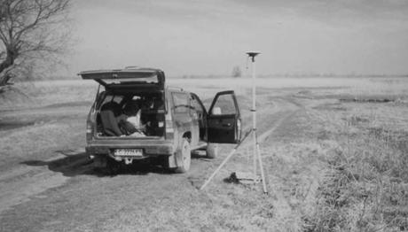
The surveys are made by the geodetic instrument Trimble, model 4700, double frequency receivers.
The surveys are carried out in fast static regime with following results processing.
Processing
Performed by software product Trimble USA – TGO.
The reports are submitted about chord processing.
Strict adjustment in WGS 84.
Accuracy valuation by close figures by location and level.
Points accuracy valuation visualized by error ellipses.
Point mean-square errors.
The transformation parameters are deduced and network transformation is done by WGS 84 – coordinate system 1970.
SGCN (Secondary Geodetic Control Network)
It consists of 15 points. Solid signs of polyamide concrete with underground center of German company INTERMAK stabilize them.
Comparatively safe, surveyed places are selected with purpose of their long term using.
They are situated by couples at distance 200 – 300 meters at intervals of 1.5 km along the trace of inner dike to the west of the zone, as well as three triads around the inlets/outlets.
They are measured by apparatus Trimble, model 4700, double frequency receivers. The surveys are carried out in fast static regime with following results processing.
Processing
Performed by software product Trimble USA – TGO.
The reports are submitted about chord processing.
Strict adjustment in WGS 84.
Accuracy valuation by close figures by location and level.
Points accuracy valuation visualized by error ellipses.
Point mean-square errors.
The transformation parameters are deduced and network transformation is done by WGS 84 – coordinate system 1970.
1.4. Area mapping
With the purpose of complement of the existing digital mapping design of the territory surveys are made with GPS receivers – Trimble 4700 double frequency high-accuracy geodetic receivers.
Kinematic real-time work regime is used.
The points of PGCN and SGCN are used for base points.
The processing is performed by software product Trimble USA – TGO (Trimble Geomatics Office).
Specific places of the territory are mapped, as well as the dike limiting territory of the zone from the north, east and south (Danube River).
So performed surveys, completed with the surveys from task 1.3 refer Belene zone, that is the right of way 15 km length and 100 m width and existing model the three components for elaboration zone map in scale M1:5000.
2. Reviewing and specifying the methodology and approach for task implementation
Measuring of base network
The coordination of the base network points is made with support of GPS surveys
Engineers and technical staff:
Eng. Ilko Georgiev
Eng Radoslav Pavlov
Ph.D. eng. Momchil Minchev
Supprot staff – two persons
Technical equipment:
GPS receivers Trimble 4700 – double frequency - 2
Processing software Trimble Geomatics Office - 1 license
Off-road car - 1
Time table of performing of measurements:
Belene : 04.04.2003 - 11.04.2003
The processing is performed from 14.04.2003 to 18.04.2003 from Ph.D. eng. Momchil Minchev
Software for processing of results
The processing of surveys, network adjustment and transformations are made with the licensed software TGO (Trimble Geomatics Office), which is in possession of the company. Plan of surveys was done in advance, with the purpose of optimization of measuring time, with the support of planning module Trimble – Quick plan, which gives the period of the day and right place in the area with the best observation conditions, according to schedule of satellites – configuration, visibility over horizon and signal intensity of the satellites.
Technology and surveying methods
The surveys are performed in Static regime with time for observation sufficient to guarantee necessary accuracy for this type of works.
On the territory of Belene this is not necessary because of existing points of NGN checked by us through direct geodetic surveys.
Accuracy of results and final results
See attachment “Reports for processing results”.
Area mapping
Method – coordination through performing of GPS high-accuracy surveys
Work regime – real-time, kinematic
Engineers and technical staff:
Eng. Ilko Georgiev
Eng. Jordan Mladenov
Support staff – two persons
Technical equipment:
GPS receivers Trimble 4700 – double frequency - 2
Processing software Trimble Geomatics Office - 1 license
Off-road car - 1
Time table of performing of surveys:
Belene : 22.04.2003 - 26.04.2003
The processing is performed from 07.05.2003 to 09.05.2003 from eng. Ilko Geogiev
Final products
The processing of surveys is made with the software TGO (Trimble Geomatics Office).
Final product – digital design of the terrain and design of the drawings in relevant scales is performed with Autocad LDD.
Reports for surveys and processing results:
Initial data
Existing points of NGN and RGN
| BELENE 2003 TT |
| No X Y H |
|
TT50 4735606.03 9422167.63 20.536 |
|
TT4 4737742.45 9417371.75 25.876 |
|
TT5 4737789.72 9418461.48 25.82 |
|
TT6 4737775.02 9419669.72 26.337 |
Existing bench marks
|
BELENE 2003 HP, GPS point, "1970", K-7 |
|
1016 4734195.437 9414927.053 27.818 |
New-established points PGCN and SGCN
1. Coordinate system 1970
|
BELENE 2003 OGM, Our GPS points, "1970", K-7 |
|
1 4737716.727 9419986.277 26.629 |
|
2 4737800.690 9419415.199 25.206 |
|
3 4736753.362 9418764.215 22.270 |
|
4 4736924.957 9418809.554 24.226 |
|
5 4735797.203 9419623.459 23.283 |
|
6 4735551.148 9419594.124 23.229 |
|
7 4734462.905 9419338.982 22.290 |
|
8 4734241.352 9419275.573 22.841 |
|
9 4733262.844 9418802.222 26.231 |
|
10 4733162.985 9419010.391 25.550 |
|
11 4733074.374 9419211.877 25.896 |
|
12 4734992.180 9426243.938 25.237 |
|
13 4735184.920 9426111.901 25.008 |
|
14 4735482.196 9425896.391 24.651 |
|
1016 4734195.437 9414927.053 27.818 |
Belene Island – Danube dike
|
|
s